


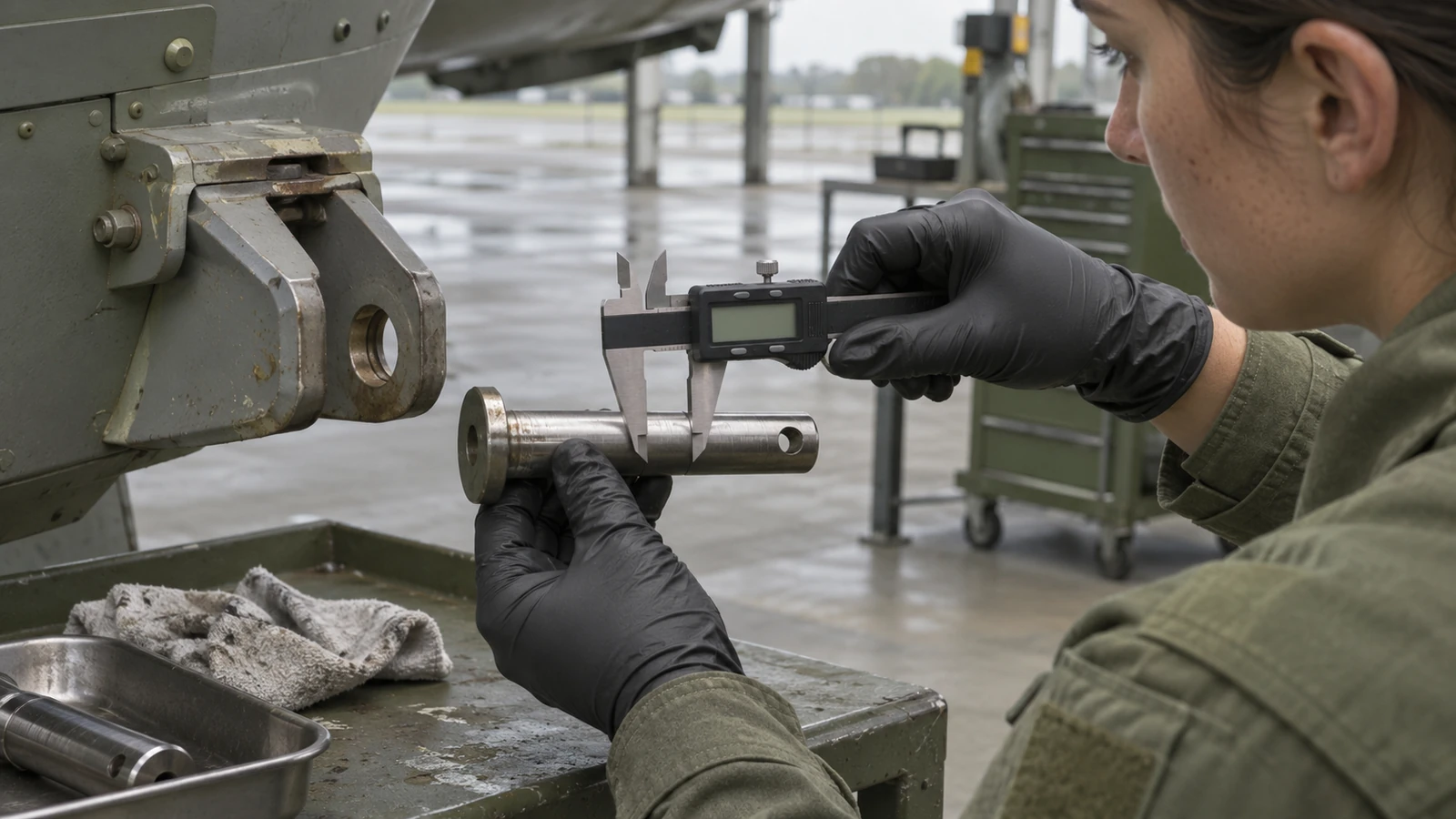
An aircraft seat lock pin participates in a small interface with large consequences for fit: the pin or plunger engages a seat track or fitting so the seat can be positioned and retained as designed. A useful prototype drawing must distinguish the pin’s locating surfaces, engagement feature, travel or retention features, and relation to the supporting housing. The article focuses on manufacturing communication and dimensional review, not aircraft maintenance or approval for flight.
Seat-track and seat-fitting designs vary. Do not infer a universal pin shape, load rating, engagement depth, or inspection limit from the term alone. The responsible design organization must supply the approved drawing, material and process requirements, and any qualification or acceptance criteria.
Define what “locked” means in the drawing
Before detailing the part, identify the intended engagement condition. Does the pin enter a track opening, a fitting feature, or another component? Which surfaces prevent lateral motion, and which features allow deliberate release or adjustment? A clear drawing separates the locking interface from the spring seat, actuator end, retention groove, or handle interface.
For an aircraft seat lock pin, the critical geometry may include the pin diameter, tip or nose form, shoulder position, travel, retention feature, and alignment to the seat fitting. These are not a standard list of mandatory dimensions; they are prompts for the design review. Only the released configuration determines which characteristics are controlled.
Use sections and detail views where the engagement interface is hidden inside a housing. Identify the part’s datum features and show how they relate to the mounting face or guide bore. A nominal dimension from a convenient outside edge may be insufficient if the pin is actually guided by a bore or sleeve. The drawing should make the functional location measurable from the same reference that represents assembly.
Control pin-to-guide alignment and engagement depth
The pin may slide through a guide or housing before reaching the seat-track fitting. Its alignment depends on the guide bore, mounting surfaces, pin straightness, and the assembly stack. If the pin axis is tilted or offset, movement may feel rough or the pin may approach the engagement opening unevenly. A drawing review should identify which part features control that relationship and which tolerances belong to the assembled mechanism.
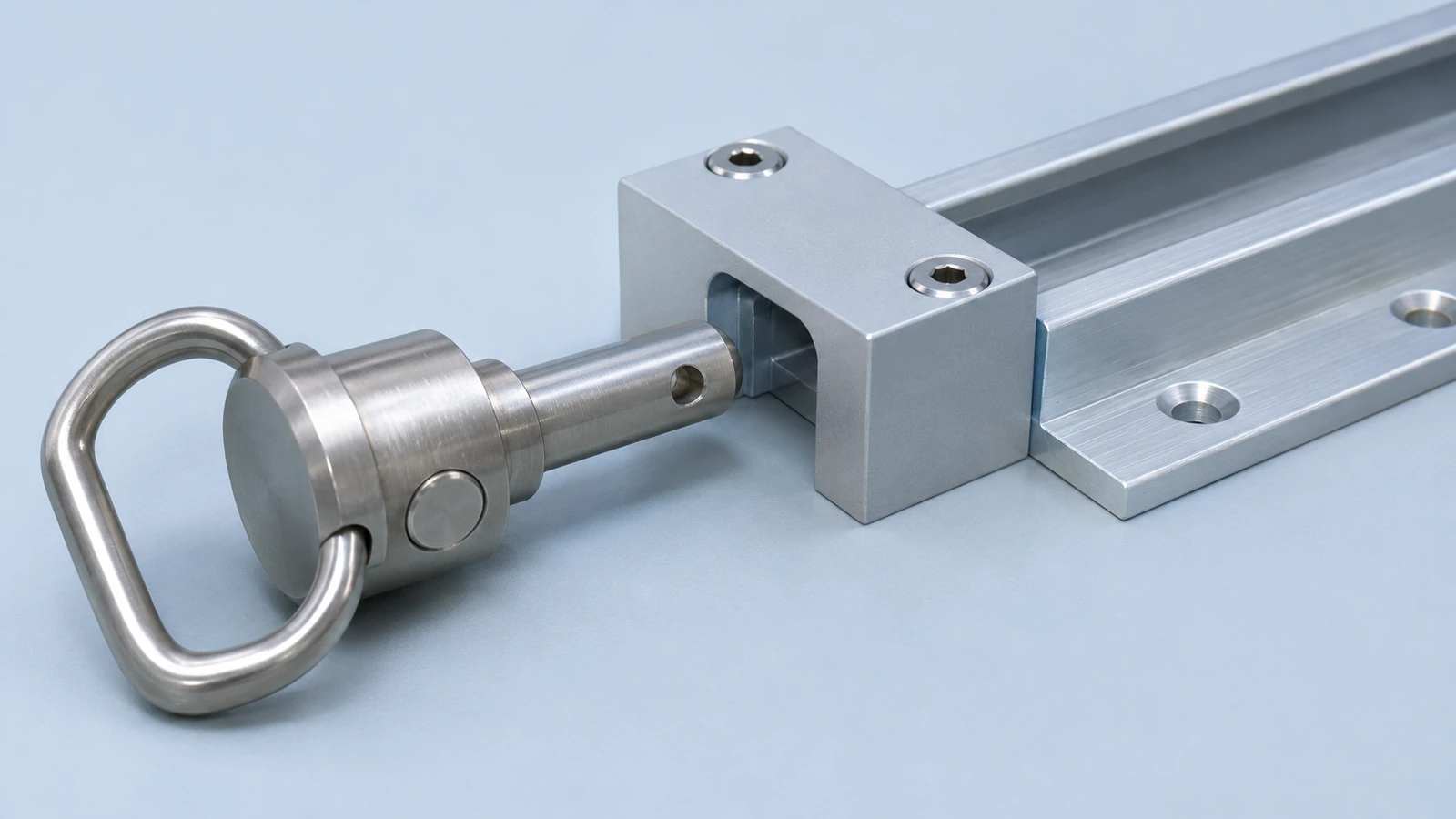
Engagement depth is a system-level question. It can depend on pin travel, track or fitting geometry, spring or actuator behavior, and structural deflection in the applicable design context. Do not copy a depth from another seat family or use an unverified service document as a universal value. The drawing owner must provide the intended range and the method for verifying it.
Consider a hypothetical prototype review: the pin meets its diameter requirement and slides in the guide, but the tip does not consistently reach the intended track feature in a fixture. The review should separate pin length and tip geometry from housing position, guide alignment, travel stop, and mating-part revision. This example is not a real aircraft case and does not prescribe an adjustment. It illustrates how to isolate the interface before changing dimensions.
Keep safety-critical context attached to the approved design
Aircraft seats and their attachments are addressed within aircraft certification and occupant-protection requirements. The FAA’s advisory material on dynamic evaluation of seat restraint systems discusses seat-track fittings and their role in an attachment load path. That context reinforces why seemingly small engagement details must be evaluated within the complete approved design rather than in isolation.
Une aircraft seat lock pin prototype can be checked for its specified geometry and fit. Such dimensional work does not establish that a seat system satisfies dynamic testing, regulatory requirements, fatigue life, or airworthiness. Those conclusions require the applicable design substantiation and verification process. A manufacturing article should not blur the difference between making a part to a drawing and approving a system for service.
Material, heat treatment, coating, corrosion protection, and traceability must also come from the approved specification. A supplier should not choose a material based on a general description or assume a finish is acceptable because it appears on another aircraft component. If a required condition is missing, it should be raised as an open input before production planning.
Plan machining and finishing around sliding surfaces
Pin features may combine turned diameters, shoulders, grooves, flats, cross-holes, or a shaped tip. The process plan should preserve the guiding diameter and the position of engagement features relative to the datum axis. The exact machining sequence depends on material, geometry, stock, finish, tolerance, and whether secondary processes are specified. No one sequence is suitable for every lock pin.
Review tool access around grooves and cross-holes, deburring requirements near sliding surfaces, and the effect of coating or heat treatment on the final dimension. An edge break may protect an assembly interface, but an uncontrolled chamfer can change how the tip enters a track feature. Identify the surfaces that require a defined edge condition and distinguish them from nonfunctional edges.
For prototype work, a drawing package should include the 2D drawing, 3D model, material and condition, quantity, surface-finish requirements, post-processing notes, and inspection needs. If the part mates with a track fitting, provide controlled mating geometry or an approved reference component when possible. A virtual model helps explain packaging, but it is not automatically a certified gauge or an acceptance authority.
Choose inspection methods that match the function
Inspection can include the pin diameter, length, shoulder location, tip geometry, straightness or runout where specified, groove dimensions, and any datum-based position requirement. A micrometer checks a local diameter; it does not verify tip alignment relative to a guide axis. A functional fixture may show whether selected parts fit together, but the fixture must represent the specified reference condition and its scope should be documented.
For an aircraft seat lock pin, agree on which characteristics are critical to the prototype review and what the report should contain. Where engagement is checked in an assembly fixture, document the fixture revision, mating part, orientation, and observed criterion. Do not convert a simple fit check into a statement of regulatory compliance. If the design requires a formal qualification test, that plan remains separate.
A useful report identifies the drawing revision, part identity, inspection setup, instrument or method, and measured characteristics. When the design changes, preserve the old data and note the revised features. This allows the engineering team to compare revisions without mistaking a different fixture or datum simulation for a geometry improvement.
Questions to resolve before requesting a prototype
- Which feature guides the pin and establishes its axis?
- Which component or datum defines the engagement condition?
- What controls pin travel, stop position, and intended engagement depth?
- Which dimensions apply before and after heat treatment or coating?
- What edge condition is required near the sliding and engagement surfaces?
- Is a mating fitting or controlled fixture available for fit review?
- Which inspection is dimensional, and which separate system-level tests are required?
For prototype machining planning, see the verified CNC machining capabilities page. If the approved drawing specifies a titanium alloy, the site’s Ti-6Al-4V material page is a relevant material-navigation resource, not a recommendation for the pin’s material. The drawing controls the choice.
Frequently asked questions
Is an aircraft seat lock pin the same as a seat-track fitting?
Not necessarily. Terminology and mechanism architecture vary. The drawing and illustrated assembly should identify the pin, guide, fitting, and track features and define their roles.
Can a pin gauge confirm correct seat locking?
A gauge may verify a specified size or selected fit. It cannot automatically establish travel, engagement depth, alignment in the installed seat, or system-level compliance.
Can a prototype shop set an engagement depth if the drawing omits it?
No. The responsible design organization must define the intended engagement and acceptance criteria. The omission should be resolved before the part is treated as released.
Does a dimensional inspection demonstrate airworthiness?
No. Dimensional inspection checks stated part characteristics. Airworthiness is established through the applicable approved design and verification process.
Source and scope
The FAA’s AC 25.562-1B with Change 1 provides guidance on dynamic evaluation of seat restraint systems and occupant protection on transport airplanes, including discussion of seat-track fittings. It is system-level guidance, not a machining drawing or universal lock-pin specification. Apply the approved program documentation to the specific aircraft configuration.

