


A crankshaft reluctor wheel provides a geometric target for a position-sensing system. Counting its teeth is only one part of defining it. The pattern’s angular reference, mounting orientation, relationship to the shaft, and compatibility with the specified sensor determine what information the system can obtain from the rotating component.
For a custom prototype, the manufacturing task is to preserve the approved target geometry and make its relationship to the shaft inspectable. This guide explains that handoff rather than an engine conversion or control-system calibration. A wheel that passes dimensional checks still needs any signal and system validation required by the responsible engineering team.
Tooth count identifies a pattern, not a complete interface
Start with the controlled pattern definition. Identify tooth or window geometry, angular spacing, any intentionally different feature, and the reference from which the pattern is clocked. Designs can use different sensing principles and target constructions, so a supplier should not assume that every wheel is a simple row of identical external teeth with a missing tooth.
Le Lingenfelter crankshaft and camshaft reference illustrates different engine-specific patterns and sensor requirements. It helps explain why a tooth-count label does not establish interchangeability. Its application information belongs to those systems and should not be generalized into a drawing for an unrelated target.
Define which direction the drawing is viewed from. An angular feature can be mirrored if one team works from the engine-facing side and another from the opposite side. Include a clear view convention and an unambiguous locating feature. A photograph of a loose wheel rarely supplies enough information to recover its intended phase.
Carry the angular reference through the mounting features
The wheel’s pattern must relate to the shaft through a defined connection. Depending on the design, locating information may come from a key, pin, bolt pattern, controlled assembly fixture, or another approved reference. The drawing should explain that relationship without requiring the machinist to infer it from the outside shape.
For a crankshaft reluctor wheel, the central bore and the target pattern can both be dimensionally correct while their angular relationship is wrong. Check the phase from the specified locating reference, not merely from a convenient tooth. If the interface allows assembly in more than one position, identify how the approved assembly process establishes the correct one.
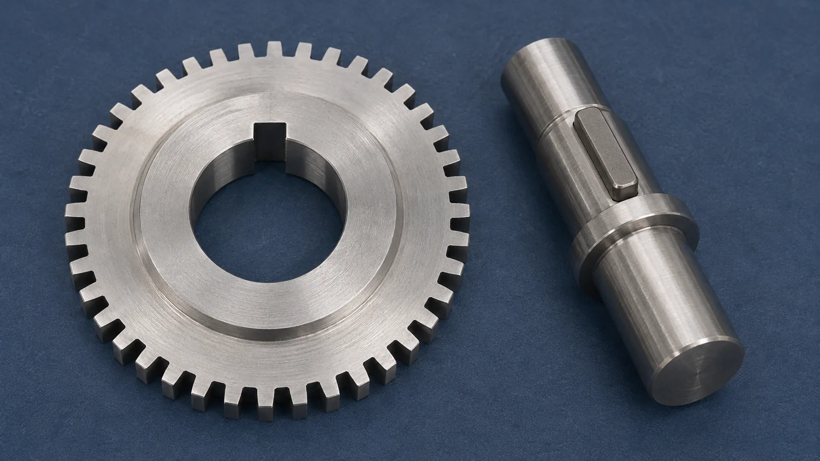
Separate radial location, axial location, and angular orientation in the review. A bore may establish centering while a shoulder establishes axial position and a separate feature establishes phase. Combining these into a vague note such as fit to shaft hides which surfaces need control. The supplier needs the drawing’s intended relationships to plan both setups and inspection.
Runout and target shape must match the sensing arrangement
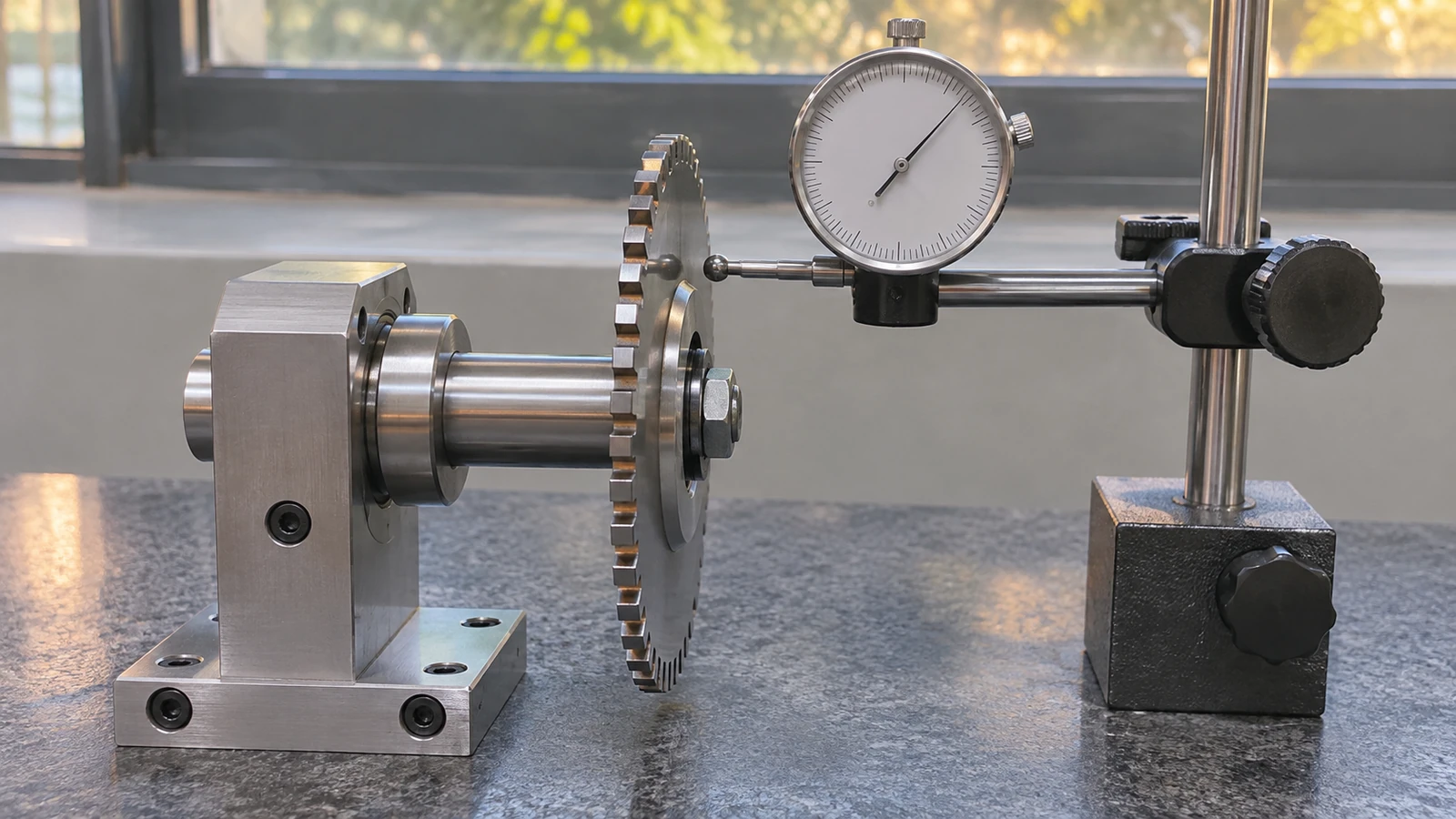
Review which target surface the sensor reads and how it is positioned in the assembly. A radial target and an axial target need different geometric descriptions. The relevant distance to the sensor can vary with wheel eccentricity, face wobble, shaft motion, or mounting condition. The design owner should define the allowable geometry and validation method for the particular system.
Nominal outside diameter alone cannot describe that variation. Identify the datum axis and the surface used for any runout requirement. If measurement occurs on a fixture rather than the actual shaft, define how the fixture simulates the mounting interface. A tight bore fit on an arbitrary mandrel does not automatically reproduce the intended installed state.
Material also belongs in the sensor-system definition. A metal target used with one sensing principle cannot automatically be replaced by another alloy, and a magnetic encoder construction is a different manufacturing problem from an ordinary machined toothed ring. Confirm the approved target specification before discussing machinability or an inexpensive substitute.
Choose a process that preserves pattern and mounting geometry
Prototype routes may include machining from stock or cutting a blank followed by machining selected features. The appropriate comparison depends on thickness, pattern detail, material, quantity, and the surfaces that need final control. Avoid selecting a route from the component name alone. Ask which operation will establish the bore-to-pattern relationship and which will establish axial faces.
Relatively thin wheels can change shape during cutting, clamping, or later processing. Support should preserve access to the target features without forcing an unacceptable free-state shape into apparent conformity. If the design requires a particular installed condition, make that condition part of the acceptance plan rather than allowing each inspector to choose a different support arrangement.
Burrs and edge treatment deserve location-specific instructions. An uncontrolled edge break can change the target silhouette, while a remaining burr can interfere with seating or inspection. Define the relevant boundaries and inspect the delivered condition. Surface processing and cleaning requirements should also be reviewed against the approved sensor target and mounting interfaces.
For the proposed metal component, the CNC machining scope provides a starting point for discussing a route. Special cutting, treatment, assembly, or electrical testing must be confirmed for the project. A machining order should state what the supplier delivers and what the system team will still need to demonstrate.
Diagnose the mismatch before altering the pattern
Imagine a hypothetical development sample whose target geometry meets the drawing, but whose system reports an unexpected position. Confirm the exact sensor, control configuration, viewing convention, wheel revision, and assembly orientation first. Then compare the physical phase reference and mounting state with the approved definition. A geometry change should follow evidence rather than an assumed tooth-count problem.
If dimensional evidence shows phase is correct, investigate the signal under the defined conditions through the responsible test team. If the mounting state differs, resolve that mechanical discrepancy before changing software settings. Keep dimensional inspection and signal verification as separate records so one result does not conceal uncertainty in the other.
This is an illustrative engineering scenario, not a Jucheng test result. It demonstrates the value of preserving reference information throughout development. Recutting a wheel to compensate for an incorrectly described orientation can create another incompatible sample, even if the immediate demonstration appears better.
Prepare the supplier handoff around the target definition
For a crankshaft reluctor wheel prototype review, send the controlled pattern model, phase reference, sensor-facing view, mounting details, material specification, required delivery state, and inspection plan. Jucheng can review the proposed component geometry and manufacturing questions against these files. Clearly identify whether the sample is for packaging, geometry evaluation, or a separately defined system test.
Frequently asked questions
Are two wheels with the same tooth count interchangeable?
Not on that evidence alone. Pattern details, phase, dimensions, mounting, material construction, and sensor-system requirements can differ. Use the controlled interface specification for the actual application.
Can the sensor gap be set from the wheel diameter alone?
No. The sensor location and the relevant installed geometry also matter. Use the system’s approved definition and checks; a nominal diameter does not establish the distance throughout rotation.
Does a dimensional report verify the signal?
No. It verifies the specified geometry in the reported condition. Signal behavior and system compatibility require their own defined evidence, including the relevant sensor and operating conditions.
What should be inspected after the wheel is mounted?
The project may require checks of phase, axial position, runout, and sensor-facing geometry in the installed state. The approved design and quality plan determine which checks are needed and how they are performed.

