


A clevis is a forked connection, but an aircraft hydraulic actuator clevis must do more than provide two ears and a pin hole. The pin axis, lug spacing, bearing faces, and actuator datum determine how the joint locates and transfers load in the larger system. A part can appear symmetric in CAD yet still create assembly difficulty if the two bores, side faces, or end interface are not controlled from a clear reference.
This article is a drawing-review and prototype-manufacturing guide. It does not establish aircraft structural allowables, fatigue life, airworthiness, supplier approval, or a universal clevis dimension. Those decisions belong to the responsible design and certification authorities and must be defined for the specific assembly.
Trace the joint from actuator datum to pin axis
Start by identifying how the actuator body or rod end locates in the assembly. The clevis may connect to a mating lug through a pin, while its base or threaded interface attaches to another component. The drawing should state which feature anchors the part and how the pin-bore axis is positioned and oriented relative to it. The two ears should not be treated as independent holes if the pin passes through them as one joint.
For an aircraft hydraulic actuator clevis, useful drawing questions include: Is the pin axis perpendicular to the intended mounting datum? Is the clear distance between ears controlled? Are the ears parallel or otherwise controlled to the assembly datum? Is there a specified bearing length or edge condition? Which surface contacts the mating lug or washer? The answers should come from the design, not from a generic clevis convention.
A dimensioned isometric or section view can clarify the intended stack-up. If the clevis has a central slot, define whether its width is measured between finished faces and identify the relevant inspection location. If the pin holes are coaxial, control them in a way that evaluates their shared axis and datum relationship according to the drawing scheme. Avoid describing a pair of holes as aligned without a measurable requirement.
Control the ear-and-pin interface as a system
Hole size, hole position, ear spacing, ear thickness, and side-face orientation influence different aspects of the joint. The pin must fit the holes as intended; the mating part must fit between the ears with the specified clearance or contact; and the assembly stack must align without forcing components into an unintended position. The drawing should separate these characteristics so the inspection report can answer each question.
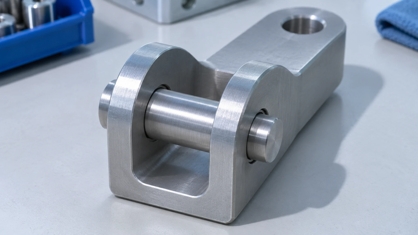
Consider a hypothetical assembly review: the pin enters both holes, but the mating lug binds between the ears. The hole diameters alone may be acceptable. The team should inspect slot width, ear parallelism, local burrs, pin straightness, and the position of the clevis relative to its mounting datum. This is a diagnostic example, not a reported Jucheng customer case. It shows why a pin-fit check should not stand in for a full interface review.
Edge distance is another design-controlled relationship. It may affect how the hole is positioned within each ear, but there is no universal edge-distance value suitable for every load, material, or aircraft configuration. The engineering authority must define the design basis and acceptance criteria. A prototype supplier should flag missing or conflicting dimensions instead of selecting a structural value.
Make the machining sequence preserve the paired bores
The forked shape can create access and fixturing questions. Depending on the geometry, the two ears may need support while the slot is machined, and the bore operation must preserve their relationship. The appropriate sequence depends on stock, material, reach, wall thickness, tolerance, and available process. Rather than prescribe a universal operation order, a review should identify how the part will be held, how the pin axis will be created, and how any setup transfer will be verified.
For an early prototype, the team can discuss a stable datum face, a method to establish the base axis, the slot and ear finishing sequence, and whether the paired bores are produced in one setup or referenced between setups. Each option has tradeoffs. One setup may help preserve relative position but may limit tool access; a second setup may improve access but adds a datum-transfer question. The released design and process capability decide which approach is acceptable.
Where the drawing calls for surface treatment, shot peening, coating, or another operation, clarify which surfaces are masked, which dimensions apply before or after treatment, and who performs the process. Do not assume an aerospace process or supplier approval based on the component name. The applicable specification and approved supply chain must be identified by the customer.
Keep material choice and strength evidence with the design owner
An aircraft hydraulic actuator clevis may be made from different materials depending on the architecture, load path, environment, and weight constraints. The part name does not identify its alloy or heat treatment. The procurement drawing should include the required standard, grade, condition, product form, and any process or traceability requirements. If that information is missing, it is an open design input, not a choice for the machinist to invent.
Dimensional prototype inspection can verify specified geometry. It cannot by itself demonstrate fatigue life, structural margin, or airworthiness. Those conclusions require approved analysis and testing under defined conditions. The article’s manufacturing discussion is limited to how a drawing communicates interfaces and how a prototype plan can preserve them.
For a relevant process overview, the verified CNC machining capabilities page describes milling and turning scope. Depending on the approved drawing, the Ti-6Al-4V machining page may also be relevant as material navigation. The link is not a recommendation that this clevis should use that alloy; design authority and customer requirements govern.
Specify checks that represent the actual joint
A useful inspection plan should identify the datum simulation, pin-bore size and axis, slot width, ear thickness, mounting interface, and any position or orientation controls. Choose measurement methods that evaluate the specified characteristic. A pin or plug gauge can check selected fit conditions; it may not reveal bore-axis position relative to the base or whether the two ears meet a parallelism requirement. A fixture can help reproduce an assembly reference, but the report should say what the fixture checks.
Before machining, align the inspection plan with the drawing revision and acceptance criteria. Decide whether the report needs actual values, pass/fail results, material documentation, or dimensional balloon references. If only critical features are being reported, identify those features. A concise report with a clear datum setup can be more actionable than a large collection of unreferenced measurements.
For a design iteration, retain the same datum and measurement approach when possible. If the setup changes, document it. This helps determine whether a fit change came from geometry, process, mating-part revision, or measurement method. It also keeps a prototype review distinct from qualification or certification evidence.
Review these drawing questions before release
- Which surface or feature locates the clevis on the actuator assembly?
- How is the pin-bore axis controlled relative to that datum?
- Are the two bores treated as a common axis, and is that requirement measurable?
- What controls ear spacing, parallelism, and the mating-part clearance?
- Are edge conditions and post-treatment dimensions clearly assigned?
- Which material, condition, process records, and traceability requirements apply?
- Which inspection results are needed for the design review, and what is outside the prototype scope?
Frequently asked questions
Should both clevis holes be machined in one setup?
That may be one process option, but the correct method depends on access, geometry, tolerance, material, and the approved process plan. The drawing must define the required bore relationship; the supplier can then review how to achieve and verify it.
Does a pin gauge prove the clevis will assemble?
Not by itself. A gauge can assess a selected hole or fit characteristic, while assembly also depends on bore position, ear spacing, mating-part dimensions, and other defined interfaces.
Can a prototype report establish airworthiness?
No. A dimensional report documents selected characteristics. Airworthiness and structural substantiation require the applicable approved design, analysis, tests, and regulatory process.
Which alloy should be used?
The responsible design authority must specify the alloy and condition. The part name does not provide enough information to select a material or heat treatment.
Sources and scope
For an example of seat-track fitting load-path considerations in a different aircraft attachment context, see the FAA’s AC 25.562-1B with Change 1. It is not a clevis design standard and is cited only to illustrate why attachment details and load paths must be handled within the applicable approved design basis. The specific clevis drawing and program requirements remain controlling.

