


A piston is not adequately defined by one outside diameter. Automotive piston machining must preserve the specified skirt profile, ring-groove geometry and pin-bore relationship, as well as any crown features and finished surface requirements. Those characteristics serve different interfaces, so they need different inspection questions.
For an OEM development or custom component project, begin with the controlled design and the purpose of the build. A sample used to check assembly space has a different evidence requirement from a component intended for an engine test. Manufacturing conformity and successful operation are connected, but one does not automatically prove the other.
One component presents several different fits
The skirt interacts with the cylinder, the ring grooves locate the rings, and the pin bores connect the piston to the pin assembly. The crown may introduce additional geometry whose purpose and limits are controlled by the engine design. A quotation should identify all applicable features rather than reduce the work to turning a cylindrical blank.
A requirement matrix is useful because the same inspection method may not answer every question. It also makes omissions visible before production. The examples below identify manufacturing review topics; they do not prescribe engine clearances or substitute for the drawing.
| Feature group | Question for manufacturing | Question for inspection |
|---|---|---|
| Skirt | What profile and finished condition are specified? | Where and how is the accepted profile measured? |
| Ring grooves | How are the flanks, root and edge conditions produced? | Which dimensions and surfaces require separate results? |
| Pin bores | How is their shared reference maintained? | Are size and axis relationships both covered? |
| Crown features | Which contours and remaining sections control the design? | Can the specified geometry be accessed and verified? |
These decisions belong within the broader automotive manufacturing processes. The piston-specific task is to preserve several interfaces on a component that changes stiffness as material is removed.
A single diameter reading can misrepresent the skirt
Use the specified profile rather than assuming the skirt must be a simple cylinder. A design can define different geometry along the length or around the circumference. The correct measurement positions and orientation must follow that definition. Reporting the largest convenient diameter can conceal whether the intended profile was produced.
Temperature and measurement condition also matter. Agree on the environment and any conditioning needed for the applicable requirements. Measurements taken immediately after a manufacturing operation may not be directly comparable with those taken under the specified inspection condition. Record enough context to make comparisons meaningful.
Workholding must provide access without forcing the skirt into a misleading shape. As the internal material is removed, the component may respond differently to the same clamping arrangement. Evaluate the finished part in the condition required by the drawing, including any relevant free-state requirements.
For a prototype, a simplified outer profile may be appropriate only when the design owner explicitly approves that simplification for the intended study. Mark the limitation clearly. A convenient fit model should not later be treated as a representative running component without the necessary engineering review.
Ring grooves deserve more than a width check
Groove width is one requirement, but the root geometry, flank condition, location and edge transitions may also affect the intended interface. The manufacturing plan should identify those characteristics individually. Using one tool does not make them one inspection characteristic.
The public scope of SAE J2275 addresses ring-groove terminology and dimensional definitions. It is a useful reference for understanding why groove characteristics need precise language. Its applicability and contractual use must be established for the actual product; a general reference is not a substitute for the released design.
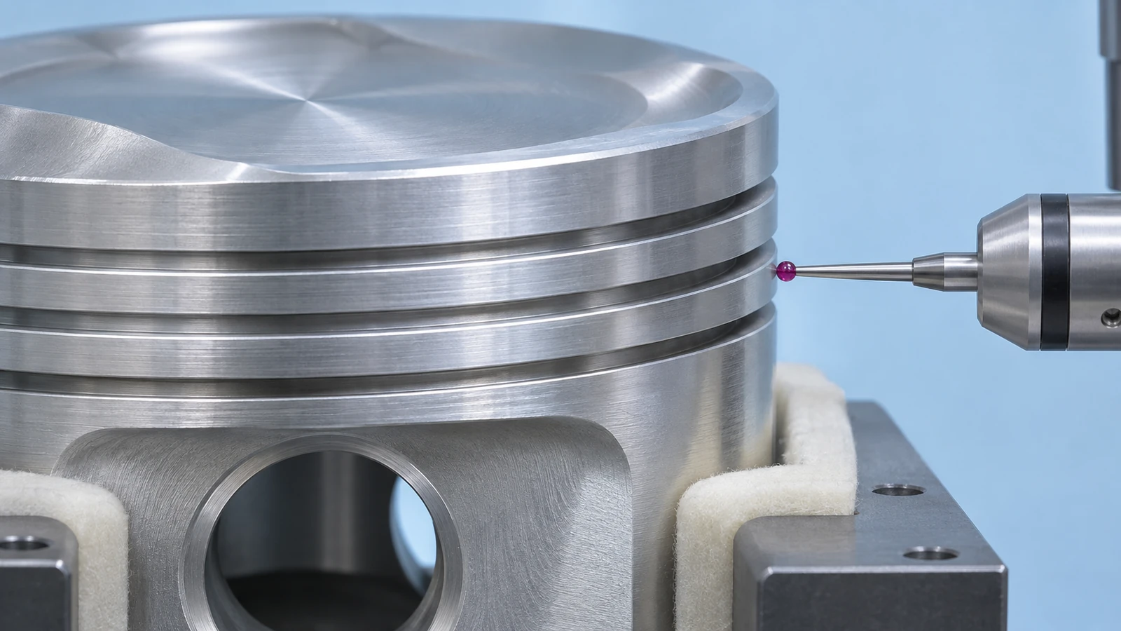
Plan how the tool reaches the groove and how chips leave the cutting zone. A process that produces the nominal profile can still leave an unacceptable burr or surface condition. Inspection should be capable of evaluating the specified surfaces and edges rather than relying solely on a ring being pushed into place.
Avoid informal hand blending at the groove mouth or root. An apparently minor correction can alter a defined transition or remove material from a functional surface. If an edge does not meet the requirement, use an authorized correction and verify the resulting geometry. The goal is a controlled groove, not simply a visually polished one.
Surface treatment can create another dimensional boundary. Identify which groove requirements apply to the bare part and which apply to the delivered condition. Masking, allowance and final inspection must agree with that interpretation.
Tie the pin bores to the rest of the drawing
The two pin-bore regions need a defined relationship to each other and to the piston鈥檚 controlling reference. Bore size alone does not establish alignment or any specified offset. A model may show that offset visually, but the drawing and inspection plan must explain how it is controlled.
Fixture access can become difficult as the internal geometry develops. Plan the sequence so that the required references remain available when the bores and surrounding features are finished. If the setup changes, document the datum transfer and verify the resulting relationship.
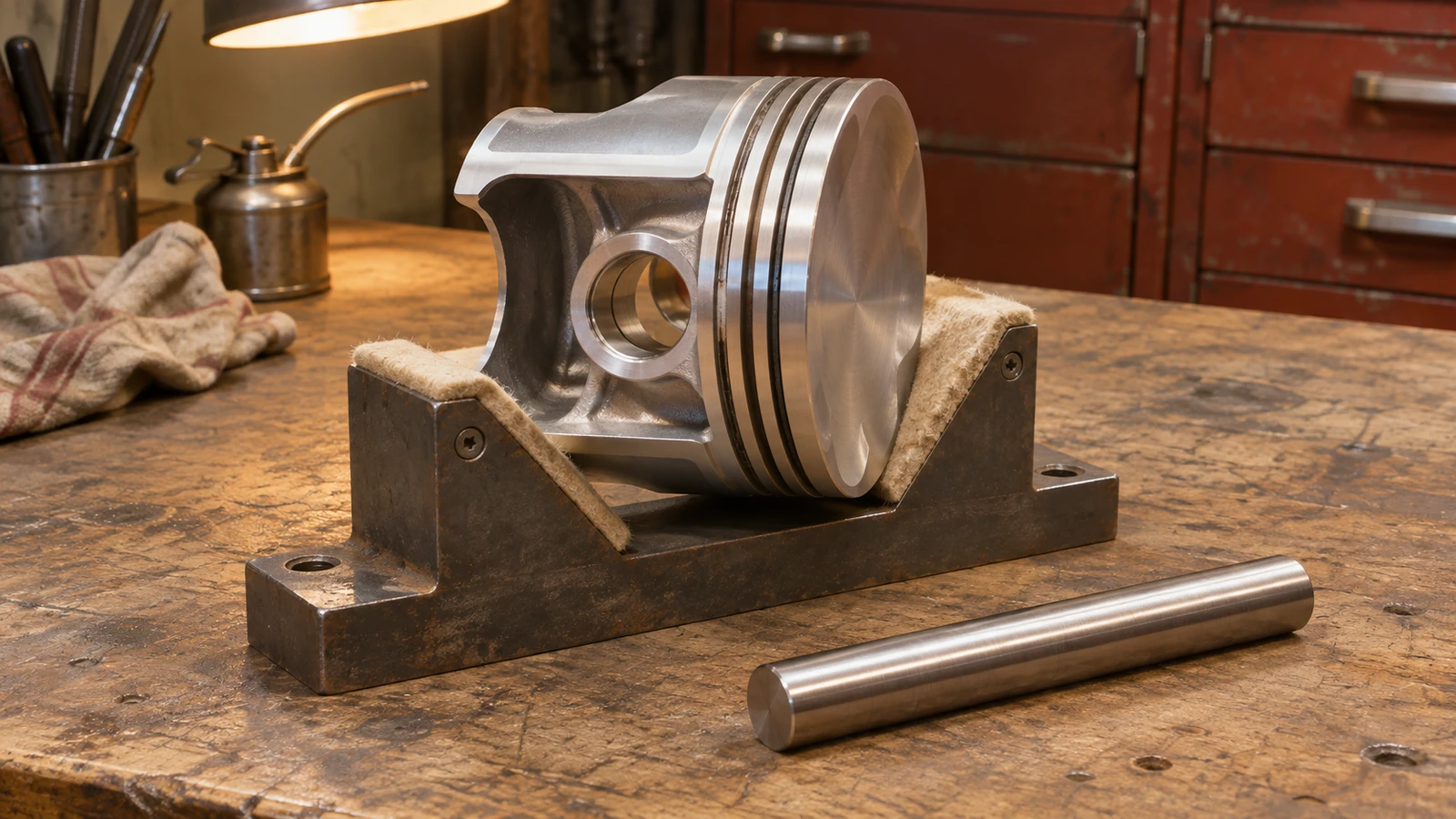
Separate local surface requirements from geometric requirements. A smooth-looking bore can be the wrong shape, while a correctly located bore can still have an unacceptable finished surface. Choose inspection methods that address each requirement and identify any limitations in their coverage.
The pin, retention features and connecting components belong in the interface review where relevant. The supplier does not need to design the entire assembly to machine the piston, but it does need an unambiguous definition of the features being supplied and the intended acceptance condition.
Match the blank and finishing route to the build purpose
Casting, forging and machining from a suitable blank can support different development and production needs. Route selection depends on geometry, material specification, quantity and the questions the part must answer. A billet prototype can support a rapid design change, but it should not be assumed to reproduce all characteristics of another intended production route.
For an aluminum design, review the specific alloy, product form and condition alongside the aluminum machining requirements. Other piston designs may use a different specified material. Do not select an alloy solely because its machining behavior or availability makes the quotation easier.
The order should state whether the supplier receives a finished-condition blank or performs intermediate processing. If a required operation can change dimensions, leave an appropriate and controlled plan for subsequent finishing. Inspection at the wrong stage can produce an accurate report for a condition that is no longer delivered.
Discuss finition de surface by region. The crown, skirt, grooves and pin interfaces may have different requirements. A single phrase such as coated piston is insufficient to define coating location, dimensional interpretation, masking or acceptance. Required treatments and their sources should be confirmed for the actual order.
Cleaning and protection should follow the finished geometry. Thin edges and accessible grooves can be damaged during handling even after machining is complete. Packaging should preserve the accepted surfaces and keep the component identity linked to its inspection and material records.
Use the prototype review to make a decision
A useful prototype review starts with the question the build was intended to answer. Was it an assembly check, a manufacturing feasibility study or a component intended for an approved test program? Evaluate the result against that purpose and identify what remains unproven. A successful dimensional inspection is valuable without being described as proof of every operating condition.
For a manufacturing review, compare the planned route with what actually occurred. Note where access required another setup, where finishing stock was difficult to control and where inspection needed a different approach. These observations can inform the next revision without turning one sample into an unsupported production-capability claim.
Jucheng Precision can review a prototype manufacturing request using the controlled model and drawing, specified blank and material condition, quantity and inspection scope. Highlight the skirt-profile definition, groove requirements, pin-axis relationships and any finished-surface specifications before the work is quoted.
The delivery discussion should end with identifiable evidence: the correct revision, traceable material, results for the required characteristics and records for any specified processes. That package helps the customer decide whether to revise the geometry, change the manufacturing route or proceed to the next authorized development stage. It also keeps a small prototype order connected to the practical requirements of later production.

