


Automotive flywheel manufacturing brings several requirements onto one rotating component: attachment to the crankshaft, the clutch interface where applicable, starter engagement and a defined balance condition. Producing a round part with a smooth face does not establish that these interfaces work together. The drawing must identify which features locate the component and what condition is accepted after all manufacturing operations.
This guide concerns new components made to an approved design. Resurfacing a used flywheel introduces different questions about wear, remaining section and service limits. Those questions belong to the vehicle or component manufacturer’s repair instructions, not to a new-part machining allowance.
Define the delivered assembly before quoting
Start by identifying exactly what is supplied. A one-piece flywheel, a flywheel with a separate friction insert, and an assembly with an installed ring gear are different manufacturing deliverables. Their drawings should state the relevant interfaces, attachment details and final inspection condition. A drawing for one piece cannot silently become an assembly specification.
The commercial scope should also identify who owns the design, who supplies mating components and who authorizes changes. A machine shop can review tool access and manufacturing sequence without being responsible for defining an engine’s operating envelope. Unclear responsibilities often appear late, when a sample fits but the customer still needs evidence that was never included in the order.
Place this work within the broader automotive manufacturing processes. The important decision is which operations establish the final part and which subsequent operations can change it. Include externally supplied processes in that discussion rather than treating them as invisible steps between machining and delivery.
Material and blank route change the machining plan
Specify the material grade, product form, condition and required records. Steel, cast iron and aluminum-based designs should not be treated as interchangeable because all can be turned on a lathe. Material selection belongs to the approved design and reflects requirements beyond machinability, including the intended thermal and mechanical environment.
A machined prototype from stock can help evaluate geometry and assembly access. It does not automatically represent a cast or forged production route. If the prototype uses a different blank, record which development questions it can answer and which remain open. That distinction is particularly important when customers compare a small prototype purchase with a later production quotation.
For a design using an aluminum body, the aluminum alloy machining review should include any separate wear surface and its attachment. Confirm whether the supplier machines the body only or delivers the completed assembly. Adding an insert later can affect the final acceptance sequence, even if the body dimensions remain unchanged.
Discuss stock allowance and access while the blank is still being selected. Excess stock can increase machining effort, while inadequate allowance can leave no practical way to establish a required face after an intermediate operation. The right allowance is project-specific; an arbitrary universal value is not a manufacturing plan.
Follow the reference from the crankshaft interface
Identify the locating feature and mounting face used by the drawing. The bolt pattern may secure the component without being the sole locating feature. Inspection must follow the specified datum scheme rather than an operator’s most convenient chucking surface.
Plan how that reference survives setup changes. If the first operation produces a locating bore and face, the second fixture should reproduce the intended relationship without damaging those surfaces. Chips beneath a seating face or inconsistent contact can create apparent part variation that actually originates in the setup.
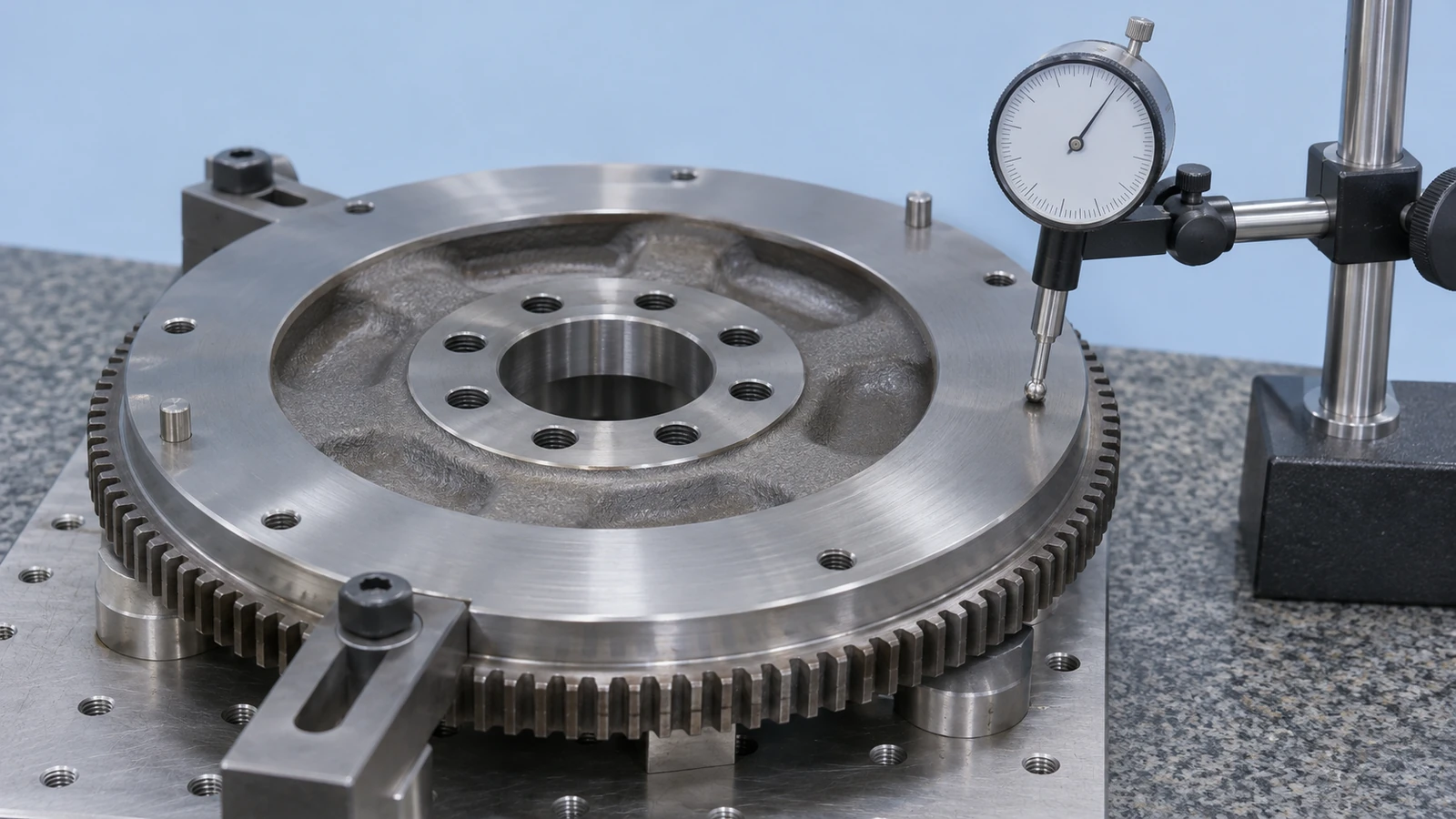
Check access to the mounting holes, recesses and transitions before committing to a route. A feature can be easy to rough but difficult to finish or measure after surrounding geometry is completed. Tool clearance should be evaluated with the real holder and fixture envelope, not only with an idealized cutting edge.
Pour automotive CNC machining, this is a useful distinction between local accuracy and assembly accuracy. Several individually acceptable dimensions do not necessarily establish the required relationship between the mounting interface and friction face. The inspection plan must explicitly address that relationship.
Separate face geometry from surface condition
Flatness, axial runout and surface texture describe different characteristics. The drawing and inspection procedure should make clear which are required and how they are evaluated. A surface can look evenly machined while still failing a geometric requirement, and a geometrically acceptable face can have an unsuitable surface condition.
The friction interface should be reviewed with its mating component and the accepted finish requirement. Avoid specifying a visually attractive finish as a substitute for the required texture. Manufacturing marks, edge transitions and any prohibited surface treatments need a clear interpretation before the finishing operation is chosen.
| Review item | What it establishes | What it does not establish alone |
|---|---|---|
| Mounting reference | How the part is located for evaluation | Acceptable friction-face texture |
| Face geometry | The specified shape or relationship | Correct final assembly balance |
| Surface requirement | The accepted delivered surface condition | Compliance with every geometric tolerance |
| Balance requirement | The defined rotating condition and acceptance result | Material suitability or complete product qualification |
This separation prevents one inspection result from becoming a catch-all approval. Record the method and stage for each characteristic, especially where the final assembly differs from the individual machined part.
Put balancing at the right point in the route
The order should define the balance requirement, the configuration being evaluated and the allowed correction method. Do not assume that every flywheel design calls for the same balance strategy. Engine architecture and the controlled specification determine the required condition.
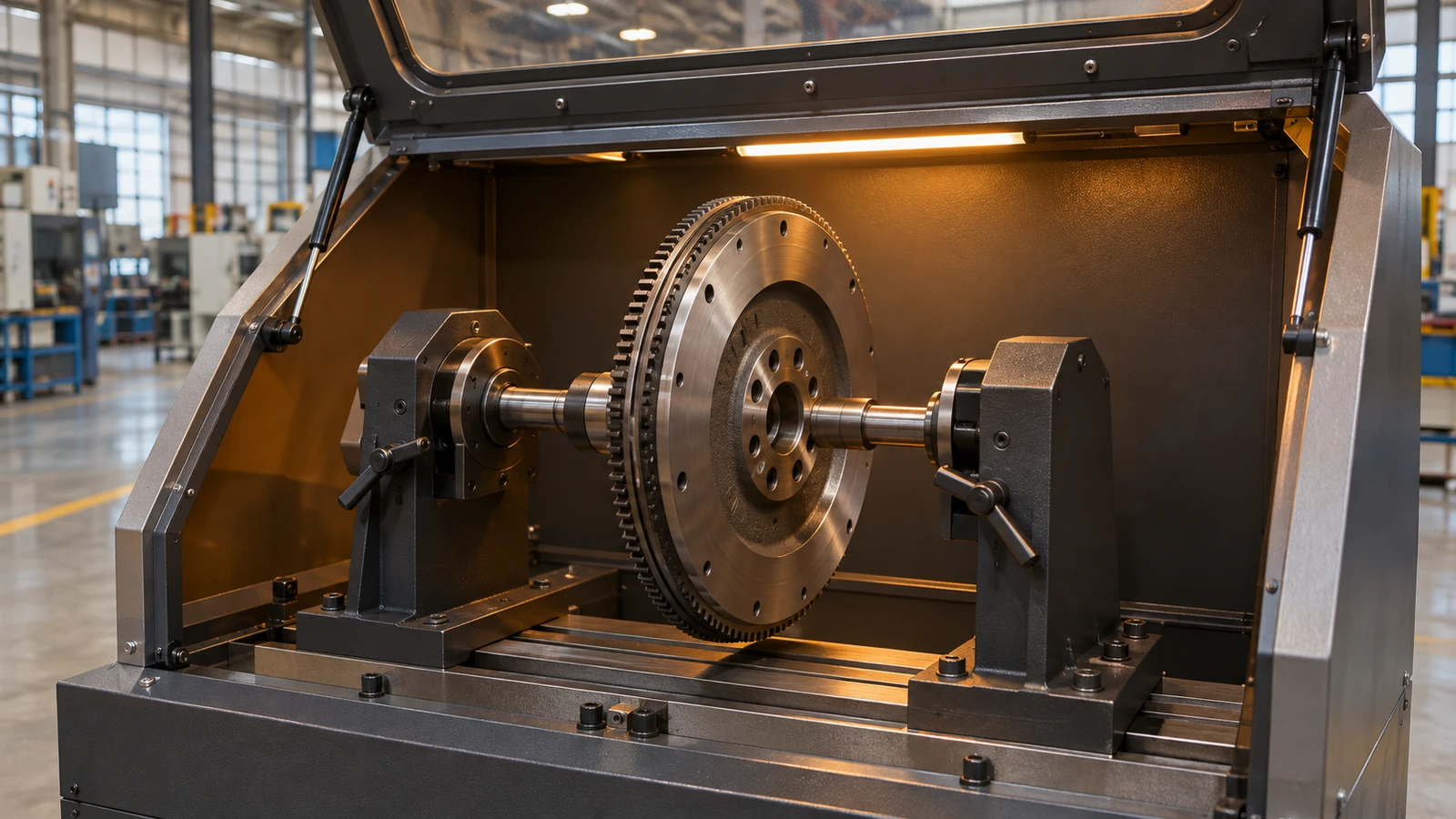
Balance correction can involve material removal, so permitted locations and remaining sections must be controlled. A supplier should not choose a convenient drilling location that conflicts with a mounting feature or another design requirement. If correction limits are absent, resolve that gap with the design owner before cutting.
Identify which components and hardware are present during the accepted check. A result obtained before a required ring gear or insert is installed may not describe the delivered assembly. Similarly, replacing hardware or reworking a component afterward can require review of the previous result.
The inspection package should distinguish dimensional inspection from balancing and any separate validation activities. Do not label a dimensional report as proof that a flywheel is qualified for every intended operating condition. Each result answers a defined question, and the customer needs to know what was actually tested.
Send a package that makes the next decision possible
A practical RFQ contains the controlled model and drawing, material and blank condition, quantity, assembly scope, finish requirements and inspection deliverables. Include the balance specification where it is part of supply, together with any approved process sources or customer-controlled requirements. Highlight unresolved items rather than leaving them hidden in email history.
Jucheng Precision can review the manufacturability of the defined component and discuss an appropriate fabrication de prototypes scope. A geometry sample, an assembly sample and a component intended for an authorized test program require different levels of evidence. Agree on the purpose before the sample is made.
At delivery, keep part identity, revision, material records and inspection results linked. Protect the locating surfaces and friction face during packaging, and identify any approved deviations clearly. The useful outcome is a component with an understandable acceptance record, so the customer can decide whether to refine the design, repeat the build or move to the next development stage.

