


Why the locking pattern governs more than hole position
An intramedullary nail is a long orthopedic component whose geometry must be interpreted as a connected system. The shaft, through-bore if present, locking holes, end features, and transitions share a common reference. A hole can meet its diameter requirement yet be out of position relative to the nail axis or another hole. A bore can be open at both ends but still deviate in straightness or finish if the design controls those characteristics.
Intramedullary nail machining begins with the current drawing and material specification. This article covers manufacturing planning for a customer-defined orthopedic component, not clinical selection or surgical guidance. The device manufacturer remains responsible for design validation, regulatory decisions, and acceptance criteria. A machining supplier can help translate the specified features into a process and inspection plan.
For the broader medical-device manufacturing context, see the medical device industry page. This article narrows in on how long geometry, holes, material condition, and finishing affect the manufacturability of a nail-shaped part.
Convert the drawing into a feature and datum map
Identify the nail’s longitudinal axis, end references, locking-hole axes, any slots or flats, and the relationship between those features. If a cannulated design is specified, include the bore diameter, straightness, surface condition, and any relationship to the external profile that appears on the controlled drawing. Do not assume every nail is cannulated or that all designs share the same locking pattern.
The datum scheme affects workholding and inspection. A cylindrical component may be located by a centerline, a defined end face, a ground reference, or a dedicated fixture. The drawing should show how angular orientation is established when holes are not all in one plane. A feature map that ties each controlled dimension to a datum reduces ambiguity between design, machining, and inspection.
| Feature group | Drawing question | Manufacturing evidence |
|---|---|---|
| Longitudinal profile | Which axis, straightness, or profile characteristics are controlled? | Measurement method and supported condition |
| Locking holes | How are position, angle, spacing, and hole form related? | Coordinate record or qualified functional fixture as specified |
| Cannulation, if specified | Are size, continuity, straightness, or surface requirements defined? | Bore measurement and passage/cleanliness check per plan |
| Ends and transitions | Which chamfers, radii, threads, or attachment features are critical? | Profile, edge, thread, and revision-controlled inspection |
Manage long bores and slender geometry
Long parts magnify setup and tool deflection issues. A slender blank may bend under cutting force or clamp pressure; a long internal bore can wander if the drilling or boring method is not matched to the stock and length. The process plan should define how the material is supported, how the part is rotated or indexed, and how straightness is evaluated. The appropriate route depends on geometry, alloy, heat-treatment condition, and the specification.
If a bore is present, plan its creation and finishing as an operation with its own controls. Chips must be evacuated, and the entry and exit edges should match the drawing. If the outside profile is machined after the bore, workholding must avoid crushing or distorting the wall. If an intermediate heat treatment or stress-relief step is specified, measurements before and after that step may be needed to understand dimensional movement.
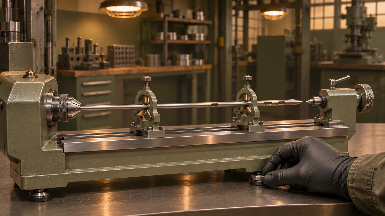
The process sequence may use turning, drilling, milling, and grinding or other finishing steps as the print requires. No single sequence suits every nail. The operation plan should state which datums are created first, how the part is re-located, and which characteristics are verified before a later operation makes them harder to reach.
Machine locking holes without losing their relationship
Locking-hole position is a multi-axis problem. The location may be controlled along the nail length, around its circumference, and relative to the nail axis. A fixture that only controls axial spacing can miss angular orientation. The drawing should make the reference plane or clocking datum explicit, and the machine setup should provide a repeatable way to index each feature.
Hole-making operations should account for burrs at entry and exit, especially where a hole intersects an internal bore. Deburring must satisfy the drawing without changing the hole diameter or edge profile. If the nail’s design includes multiple hole sizes or angles, inspect a representative sample or each feature as required by the customer quality plan. Avoid generalizing acceptance values from another product family.
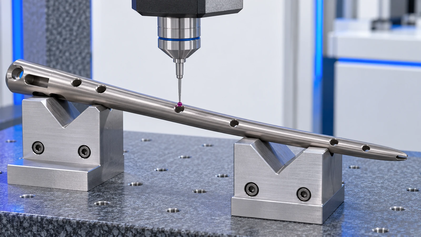
A dedicated fixture can support repeatable inspection, but its datums must match the drawing. CMM or optical methods may be useful for feature location, while pins or gauges may confirm a specific size. The inspection report should distinguish which method verifies hole size, which verifies position, and which checks angular relationship.
Choose the material route from the specification
Material and condition must come from the approved design documents. Titanium alloys and implant-grade stainless steels may be specified for different designs, but they have different machining behavior and documentation requirements. The supplier should verify the grade, condition, and lot records against the purchase specification. Do not replace a specified grade with a broadly similar alloy based on machinability alone.
Material behavior affects tool selection, cutting sequence, burr formation, and finishing. A high-strength alloy may require attention to work hardening and tool wear; a long component may need support and stress control independent of alloy. The route should preserve material traceability and separate raw-material certification from inspection results on the finished part.
The site’s titanium CNC machining page et stainless steel machining page are relevant when a drawing specifies those material families. The project documents should still identify the exact grade, condition, and applicable requirements.
Coordinate finishing, cleaning, and inspection
Surface finish and edge conditions should be stated for the features where they matter. A smooth longitudinal surface, a bore, a locking hole, and an end transition may have different requirements. If polishing, passivation, coating, or another post-process is specified, record its sequence and any masking boundaries. Measure critical dimensions at the stage required by the print, especially if finishing can change them.
Cleaning controls should be defined by the device manufacturer’s specifications. Machining residue, chips, polishing media, and handling contamination need an agreed removal and verification approach. A supplier should not claim sterilization or device validation unless that work is explicitly within scope and documented.
Inspection should connect dimensions, material records, and process revision. First-article evidence can confirm that the selected route produces the specified characteristics on the sample. Production monitoring and lot release should follow the customer’s quality plan. The evidence package should state the drawing revision and identify any characteristics not measured.
What a nail machining RFQ should define
A useful RFQ contains the current drawing, 3D model, exact material and condition, quantity by phase, surface requirements, inspection records, and packaging expectations. Mark the longitudinal datum, locking-hole clocking, any cannulation, end features, and critical dimensions. Identify whether the requested sample is for design fit, process feasibility, or a later verification stage.
Ask the supplier to explain the support strategy, operation order, hole-indexing method, deburring access, finishing route, and inspection approach. If the material or geometry is still under review, list alternatives separately rather than changing the drawing without approval. This gives engineering and procurement a transparent basis for comparing quotations.
FAQ
Are all intramedullary nails cannulated?
No. The presence, size, and requirements of a bore depend on the approved design. The manufacturing plan should follow the actual drawing rather than assume a universal nail geometry.
Why is locking-hole clocking important to machining?
Hole position includes angular orientation around the nail as well as spacing along its length. The fixture and inspection method need to reference the same clocking datum defined by the design.
Can a first-article report establish device validation?
No. A first-article report documents specified manufacturing characteristics for a sample. Device-level validation and regulatory responsibilities remain with the device manufacturer and its approved process.
What material should be used?
Use the exact grade and condition approved in the design and purchase specification. Do not infer a material from the component name alone.
For an intramedullary nail, reliable machining depends on maintaining the relationship among the long axis, bore if present, locking pattern, and end interfaces. A clear drawing, stable support plan, and feature-specific evidence let the manufacturing team address those relationships without substituting assumptions for device requirements.