


The interface stack defines the bracket
An engine mount bracket can look like a simple arm with several holes, but those holes connect the engine, mount, and vehicle structure. Their location and orientation influence how the assembly sits, how fasteners engage, and how load is transferred through the component. The bracket drawing should therefore be read as an interface map: identify the engine-side pattern, mount-side features, reference surfaces, and any clearance envelope before deciding how to make the part.
Automotive engine mount bracket machining needs a stable datum strategy because the mounting faces and hole axes often span different sides of a three-dimensional shape. If the part is refixtured without a controlled relationship between setups, small positional errors can accumulate. Conversely, cutting every feature in one setup may not be practical if the blank geometry, tool reach, or clamping access makes the process unstable.
Turn the drawing into a datum and interface plan
Before programming, label each interface by what it mates with. Identify the primary mounting face, secondary locating face, bolt pattern, threaded features, clearance zones, and any machined pad that carries a specified load path. The drawing should make clear which dimensions are controlled from a common datum and which features can be inspected independently. If the mounting pattern is position-controlled relative to an angled face, a simple hole-to-hole measurement may not demonstrate conformance.
Also distinguish the metal bracket from any elastomeric mount or other assembly component. The bracket supplier may machine or form the metal interfaces, while the mount itself can introduce additional assembly requirements. Keep those responsibilities visible in the drawing package so that a manufacturing quote does not imply an unrequested rubber or bonded assembly operation.
| Caractéristique | Why it matters to assembly | Drawing or process check |
|---|---|---|
| Engine-side face and pattern | Positions the bracket on the engine or powertrain interface | Confirm datum references, hole position, and thread definition |
| Mount-side interface | Controls connection to the mount or vehicle structure | Check face angle, spacing, and access for the mating fastener |
| Ribs, webs, and fillets | Affect rigidity, tool access, and material removal | Review machining clearance, radii, and blank stock |
| Clearance envelope | Prevents interference with adjacent parts | Use the assembly model or a defined inspection fixture |
Choose a blank that matches the bracket geometry
A billet-machined bracket may suit early prototypes, design iterations, or low quantities when the geometry is accessible and the material removal is reasonable. A cast blank can create a more complex three-dimensional shape closer to its final form, with CNC operations reserved for mounting faces, bores, and holes. A formed or welded sheet-metal design may be preferable when the geometry is largely plate-like and the drawing supports bends, flanges, and joined features.
Those routes are not interchangeable. Castings require review of draft, parting, stock, and local wall transitions. Sheet-metal routes require bend allowances, material thickness, weld access, and post-weld distortion planning. Billet machining needs sufficient stock, tool reach, and a realistic plan for cut time and part restraint. The production quantity and the probability of design changes should be considered alongside unit cost.
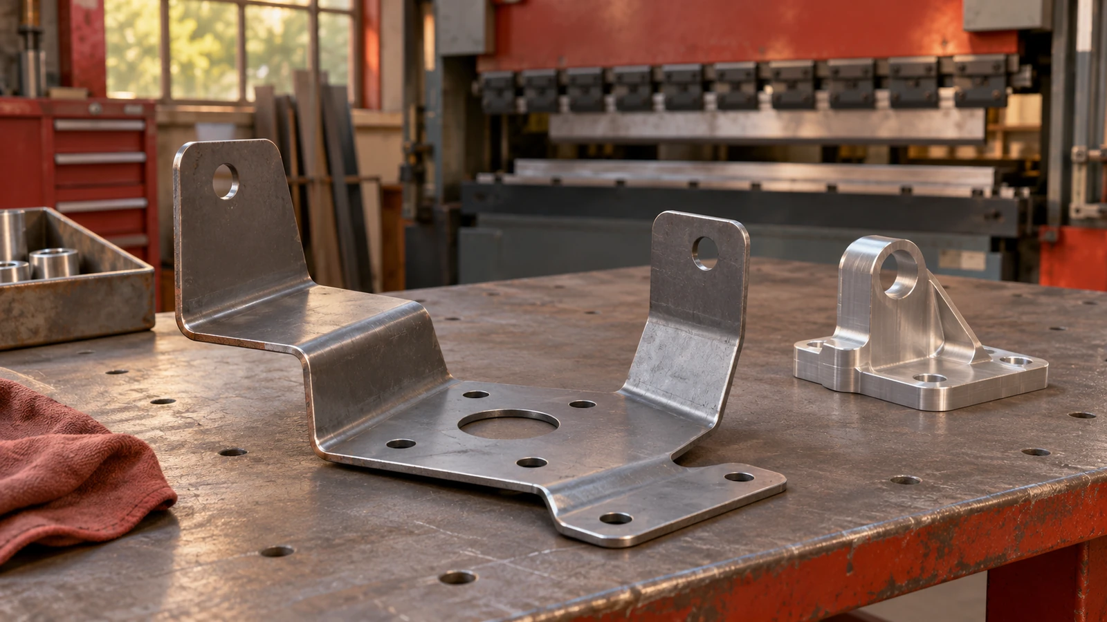
For process planning, review the site’s prototypage automobile information when the design is still being proven, and compare usinage CNC, fabrication de tôlerie, et moulage sous pression against the actual geometry and volume. These links describe manufacturing routes; they do not select a process without a drawing and quantity plan.
Keep the mounting faces related through machining
The setup should resist cutting forces without bending a slender arm or forcing a casting into a false shape. Locating pads should be robust enough to repeat, and clamping points should avoid fragile ribs or thin walls. For a part with mounting faces on different planes, decide which features should be cut in the same setup and which require a transfer datum. A probing operation can verify reference features between setups, but the fixture still has to provide stable contact.
Roughing and finishing can be separated when material stress, blank condition, or geometry makes it useful. The sequence should leave enough stock for a controlled finish pass and avoid removing material in an order that causes the bracket to spring after release. If the part is welded or formed, any post-process machining should be planned after the operations that affect its shape, unless the drawing specifies another order.
Tool access can set limits on internal corners, pocket depth, and the position of a fastener head. A DFM review should identify inaccessible surfaces before the part is quoted. The drawing can often improve manufacturability by using realistic corner radii, clear edge-break notes, and a defined inspection datum that is reachable both in production and at final inspection.
Control distortion, burrs, and finish changes
Thin arms and open sections can deflect under clamping or cutting. A dimension measured while the part is constrained may change after release, so final checks should represent the free state when the specification requires it. If a bracket is heat-treated, welded, coated, or otherwise processed after machining, define which features are measured before and after that step.
Burrs around holes and slots can interfere with fastener seating or create assembly hazards. Specify edge conditions according to function: a mounting face may require a controlled break, while a clearance feature may allow a different edge. Avoid relying on a generic deburr note where a sharp or defined edge matters.
Surface treatments should be coordinated with critical fits. Coating thickness can affect a bore, slot, or contact face. If the bracket is painted, plated, anodized, or otherwise finished, identify masking areas and the post-treatment inspection requirement. The site’s surface finishing options can be reviewed as part of the route, subject to the customer’s material and finish specification.
Verify the features that determine assembly
An inspection plan should prioritize the controlled relationships: hole position relative to datum faces, face flatness or angle, thread condition, overall envelope, and any required profile. Select gauges or coordinate measurement according to the feature. A bolt pattern can be checked with a functional fixture when its datum scheme is clear, while a coordinate report may be needed to record individual positions and angles.
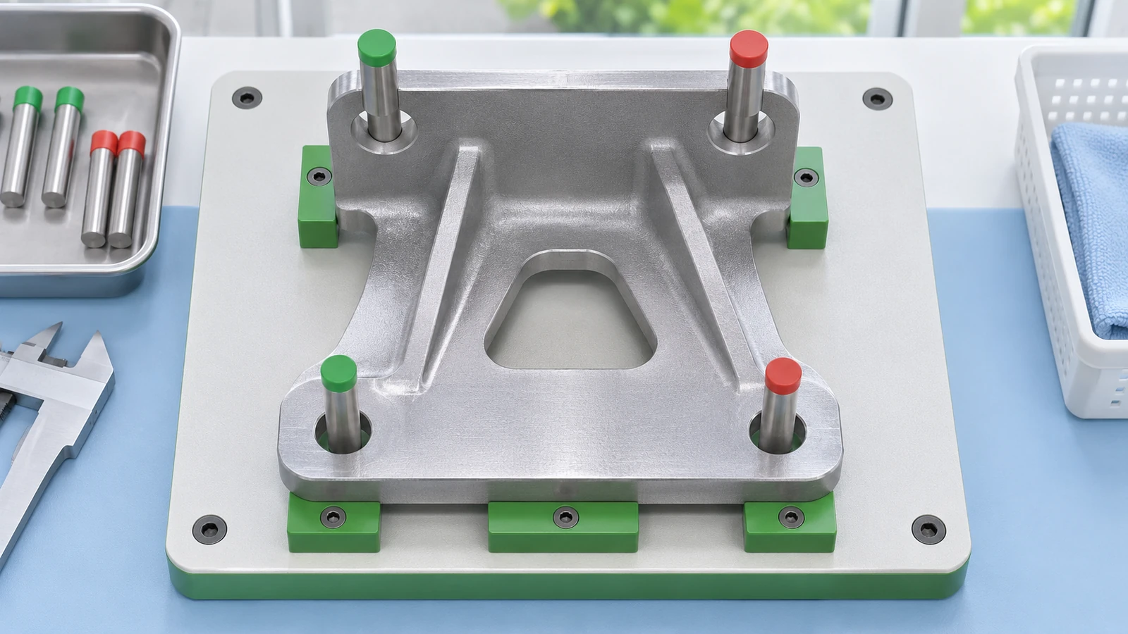
An assembly check can be useful if the mating hardware or a representative gauge is available. State which interfaces it represents and whether it checks clearance, bolt engagement, or seating. A successful fit on one sample is not automatically proof of production capability; repeatability requirements and sample plans should be defined by the project.
Keep material certificates, process records, and dimensional evidence connected to the drawing revision. If the bracket changes thickness, hole position, or material, the inspection characteristics may need to change too. This creates a traceable handoff between design, manufacturing, and procurement.
What to send with an engine mount bracket RFQ
Send a revision-controlled drawing and model, material and condition, quantity by phase, finish, and the required report package. Identify the mating interfaces, critical datum scheme, and whether the part is cast, machined, formed, or open to process recommendation. Include the assembly envelope if clearance is part of acceptance.
Ask the supplier to state the blank assumptions, setup sequence, fixture approach, finishing route, and inspection access. If the bracket is a prototype, clarify whether the goal is a fast fit check or a sample representative of a future production route. That distinction helps avoid over-investing in tooling too early or under-defining a sample that is meant to validate production.
FAQ
Does every engine mount bracket need to be CNC machined?
No. The geometry and quantity may suit machining, casting with finish machining, sheet-metal fabrication, or a combined route. The drawing and assembly requirements should determine the choice.
Why can a bracket pass hole size but fail assembly?
Hole diameter alone does not confirm location, axis, face angle, or relationship to the mating pattern. Evaluate the datum-controlled features and actual assembly interfaces.
Should finishing happen before or after machining?
That depends on the finish and which dimensions it changes. Specify the sequence, masking boundaries, and measurement stage for critical features.
A dependable engine mount bracket begins with a clear definition of the interfaces it connects. Once the blank, datum scheme, machining sequence, finish, and inspection plan follow that definition, the part can be reviewed as an assembly component rather than a collection of unrelated holes.