


A brake caliper bracket is a positioning link between a vehicle-side mounting structure and the caliper. Its bolt holes matter, but fit also depends on the relationship between mounting faces, fastener axes, rotor clearance, and the caliper interface shown on the released design. A bracket that is dimensionally plausible in isolation can still create assembly difficulty if its interfaces are not controlled from a common datum scheme. For buyers evaluating automotive brake caliper bracket machining, the useful question is how the manufacturing plan protects the complete mounting relationship.
This article addresses prototype and low-volume manufacturing decisions. It does not define brake design limits or replace vehicle validation; those requirements belong to the product owner and applicable specifications.
Contents
- Start with the caliper-to-rotor relationship
- Separate bracket function from blank choice
- Choose a route that protects the mounting datums
- Inspect the interface stack, not isolated holes
- Coordinate edge condition and finish requirements
- Ask for evidence before release
Start with the caliper-to-rotor relationship
The bracket’s functional map begins with its mating parts. One side attaches to the vehicle structure; another locates or supports the caliper. Those faces and holes establish the position of the caliper relative to the rotor and the rest of the brake assembly. The drawing may control hole position, face orientation, thickness, counterbores, threads, or a combination of these. Use the released tolerances and datums rather than assuming that a nominal bolt pattern is enough.
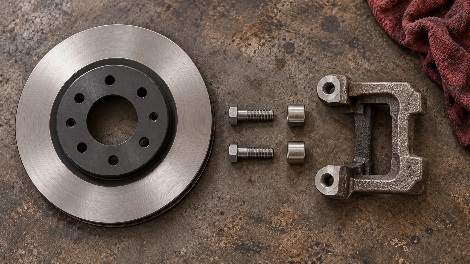
Before machining, identify the primary mounting plane, the fastener pattern, the caliper contact faces, and any clearance envelope supplied by the design team. Note which surfaces are functional and which are noncritical. This avoids spending process effort on cosmetic outline details while overlooking the face-to-face or hole-to-datum relationship that determines fit-up.
When the bracket is part of an evolving design, keep versions clear. A CAD model may show a revised chamfer while the drawing still carries an earlier hole pattern. Record the controlling revision and resolve discrepancies before manufacturing. Do not let a shop-floor assumption become an undocumented design change.
Separate bracket function from blank choice
Brackets can be produced from plate or billet for flexible development, or from a formed, forged, or cast starting shape when geometry and volume justify those routes. The appropriate blank depends on section thickness, load path, material specification, expected quantity, and how much machining is needed on the functional faces. A low-volume prototype may favor a route that permits geometry changes; a stable design may be evaluated for a more material-efficient near-net form.
Material choice is not interchangeable across brake applications. The customer specification controls alloy, temper, heat treatment, strength requirements, and any surface protection. A lightweight aluminum bracket and a steel bracket may have different stiffness, wear, corrosion, and machining considerations. The site provides CNC aluminum options et alloy-steel machining information as route references; final material selection must come from the approved design.
For a cast design, machining allowance on mounting faces and holes deserves early attention. If the casting variation leaves too little stock to clean up a datum, finishing may become unstable. If too much stock is left, cycle time and distortion risk can rise. Review the blank drawing and finishing plan together, and consider the company’s die-casting capability only when it fits the part’s approved process and volume assumptions.
Choose a route that protects the mounting datums
Workholding should support the part without forcing it into a shape that it does not hold when unclamped. A bracket with ribs, offsets, or thin arms may respond to clamping differently from a simple plate. Establish where the fixture locates the blank, how clamps avoid critical faces, and when the functional surfaces are finished. If both mounting planes are machined in different setups, document how their orientation is transferred.
A useful process review separates roughing from finishing. Roughing removes material and establishes access; finishing sets the surfaces and holes that control fit. Whether the operations are divided by setup, tool, or machine should follow the geometry and production plan. The point is to prevent a later operation from disturbing a surface that was already treated as final.
Deburr and edge-break requirements also affect fit. Burrs at a mounting face can hold a bracket off its mating surface; excessive edge breaking can remove material close to a hole or reduce a designed contact area. Specify which edges need controlled treatment, and use a defined workmanship rule for the rest. Avoid blanket finishing instructions that could alter an interface.
Inspect the interface stack, not isolated holes
| Feature group | Why it is reviewed together | Evidence to request |
|---|---|---|
| Vehicle-side mounting face and holes | Defines attachment position and orientation | Datum-based position and face checks per drawing |
| Caliper-side face and fasteners | Establishes the caliper interface | Hole pattern, surface, thread, and orientation checks |
| Clearance and edge features | Can affect assembly access and surrounding fit | Profile or dimensional checks when specified |
Inspection should reflect the drawing’s geometric controls. If hole position is defined relative to a datum plane and axis, measure it in that reference frame. If the plan calls for a CMM, identify how the part is aligned and how the relevant surfaces are probed. For simpler checks, calibrated gauges may be appropriate. A measurement without a stated datum or revision can be difficult to interpret during a supplier review.
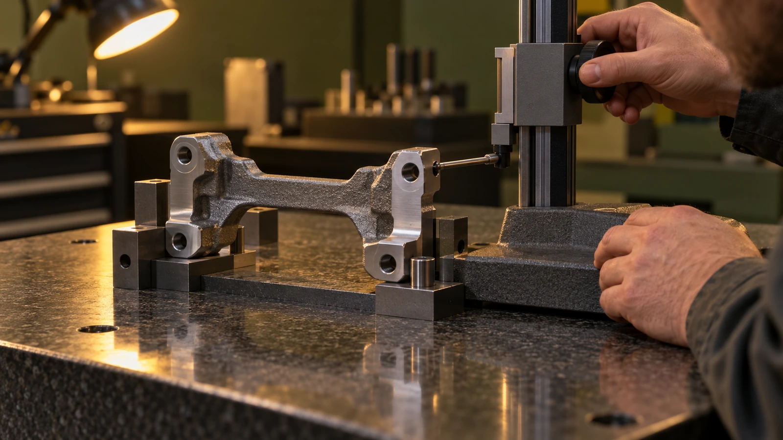
Functional fit checks may be part of the customer’s validation plan, but do not treat an informal assembly test as a substitute for dimensional acceptance. Agree whether test hardware is representative, which fasteners or torque conditions apply, and whether the check is for prototype learning or formal acceptance.
Coordinate coating and corrosion protection
Some brackets receive a coating or other surface treatment; others rely on a specified material condition or assembly environment. The approved print and finish specification define what applies. A coating can change dimensions at mating faces or holes, so the sequence should distinguish surfaces to be masked, machined after treatment, or inspected in the finished condition. These decisions should be agreed before the first sample, not inferred after an assembly problem appears.
For a finishing route, document the required appearance or performance standard, relevant masking boundaries, and the inspection state. The site’s surface-finishing service page is a starting point for discussing options. It does not establish that every finish is appropriate for a brake component; engineering approval and project requirements govern.
Ask for evidence before release
A useful RFQ includes a controlled drawing and model, material and condition, quantity by phase, critical interfaces, finish requirements, inspection records, and any customer-mandated validation. Ask how the supplier will establish and transfer datums, what setup changes are expected, and how the final inspection relates to the drawing. This makes the quote more informative than a price based only on the bracket’s size.
For a new design, a prototype can expose access, tolerance-stack, and assembly questions before the process is locked. The prototype manufacturing route can support that discussion. For ongoing automotive development, the automotive industry page connects part-level work to broader prototyping and manufacturing services.
Frequently asked questions
Is hole spacing enough to define bracket fit?
Usually not by itself. The drawing may also control mounting-face relationships, hole orientation, thickness, threads, and clearance features. Review the specified datum scheme and mating interfaces together.
Can a caliper bracket be machined from billet?
A billet route may suit development or low quantities, but blank choice depends on the approved material, geometry, production volume, and design intent. It should be reviewed rather than assumed.
Should finished dimensions be inspected before or after coating?
Follow the drawing and finish specification. If coating affects an interface, the inspection state and any masking or post-finish operation should be agreed before production.

