


An acetabular cup is a compact part with a demanding geometric relationship: the external interface, internal bearing surface, rim, and any holes or features must remain tied to the drawing’s datum scheme. “Make the sphere accurate” is not a complete manufacturing instruction. The drawing must state which surface controls the measurement, what form and size characteristics matter, and how the part is held without distorting it. This article addresses manufacturing planning for a specified component; it does not offer clinical guidance or claim that machining alone establishes device suitability. For development and supplier review, Jucheng Precision’s medical-device prototyping page is the relevant industry entry point. The project owner remains responsible for approved design inputs, material requirements, verification, and applicable quality-system controls.
Contents
- Start with the controlled drawing and component boundary
- Keep inner and outer geometry in one coordinate frame
- Plan machining sequence around access and stability
- Treat material identity as a controlled input
- Define surface requirements without vague finish language
- Build a verification plan for curved surfaces
- Make the supplier package unambiguous
- Frequently asked questions
Start with the controlled drawing and component boundary
Define whether the manufacturing scope covers a cup body, a liner, a shell, or an assembled interface. These are different parts and may use different materials and processes. Provide the revision-controlled model and drawing, including the inner and outer surface definitions, rim geometry, any fixation features, and the relationship to mating components. Do not infer a particular design from a generic product name. Separate dimensions that control assembly or measurement from reference geometry. If the inner surface is the primary reference, state how the outer surface and rim relate to it. If an outer feature establishes fixturing, show how its position is controlled after subsequent operations. This turns a shape file into a manufacturing definition and allows inspection to report the characteristics the design actually requires.
Keep inner and outer geometry in one coordinate frame
Concentricity, center location, wall thickness, rim orientation, and surface form can interact. Checking inner and outer diameters separately may not reveal a shift between them. A coordinate frame should connect the surfaces and any holes or flats. Where the drawing uses profile, position, or runout controls, the measurement strategy should match the specified characteristic rather than substitute an easier but different check. For a hemispherical or otherwise curved surface, clarify the measurement region, edge exclusion, sampling strategy, and reference alignment when those details affect acceptance. A scan can produce a dense point cloud, but data density alone does not determine whether the inspection is valid. The evaluation method, calibration, fixturing, and reporting convention all matter. Agree on these before the first article if the geometry is unfamiliar or the tolerance scheme is complex.
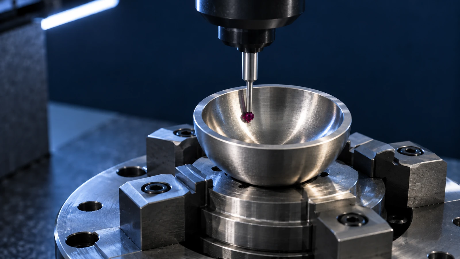
Plan machining sequence around access and stability
Curved shells can be difficult to clamp while preserving the surface being machined. A holding strategy may use a temporary datum, soft jaws, a dedicated nest, or a sequence that finishes one side before the other. The choice depends on the material, blank, geometry, and required quantities. Clamping force should support the part without forcing the rim or shell into a shape that relaxes after release. Roughing and finishing may need to be separated so stock removal does not undermine a surface already treated as final. If holes or fixation features are present, plan their order relative to the main surfaces and establish how their positions are referenced. Tool access, cutter contact, edge condition, and chip evacuation deserve attention near the rim and small features. The exact process sequence must come from the controlled model and manufacturing review, not a generic recipe.
Treat material identity as a controlled input
Metallic implant components may use specified titanium alloys or cobalt-chromium materials, while bearing components may involve other material systems. The applicable grade, product form, condition, traceability documents, and approved supplier route must come from the customer’s specification. This article does not select a clinical material or assert that one alloy is suitable for a particular indication. For machining, the material specification affects tool selection, heat generation, surface treatment, and inspection planning. Keep material identification linked to the part and revision throughout the job. If an alternative is proposed, obtain written approval before substitution. Jucheng’s medical-device materials overview provides broad manufacturing context; it does not replace the design authority’s approved material callout.
Define surface requirements without vague finish language
A note such as “polished finish” can be interpreted in several ways. State the actual surface parameter, measurement method, sampling location, and whether it applies before or after any treatment. Curved surfaces require a repeatable measurement position and a fixture that does not scratch or mask the area. If the rim or holes have separate edge conditions, specify them rather than expecting a general finish note to cover every feature.
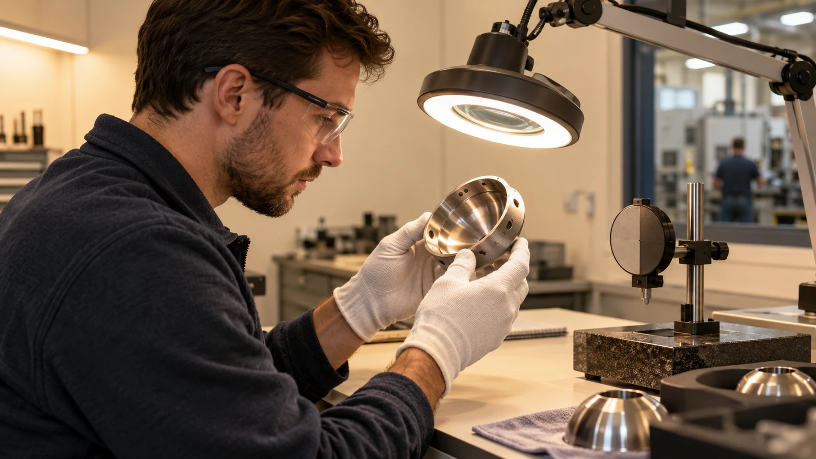
When post-processing is part of the approved route, identify which dimensions are measured before or after that stage and which areas are protected. Do not assume finishing changes only appearance; it can affect dimensions, edges, and measurement access. The surface-finishing capability page can orient a process discussion, while the drawing and approval documentation control the part requirements.
Build a verification plan for curved surfaces
Inspection may combine coordinate measurement, form measurement, scanning, gauges, and documented visual checks depending on the specified characteristics. The plan should explain how the part is aligned, where measurements are taken, how the data are evaluated, and what report format is needed. A complete scan should not be mistaken for proof that every requirement passed; the evaluation must trace back to the drawing. For first articles, agree on the critical characteristics and measurement approach before machining is complete. Consider whether the part needs to be measured free-state or in a defined fixture. Record the equipment, calibration status where required by the quality plan, part identification, material record, and drawing revision according to the agreed documentation scope. Do not claim clinical performance from dimensional inspection.
Make the supplier package unambiguous
Send the native CAD model, controlled drawing, material specification, quantity, finishing instructions, traceability and documentation expectations, and any inspection method specified by the customer. Identify whether the request is for an early development piece, design verification article, or another stage. Mark critical surfaces and datum relationships, and explain any areas where handling or fixturing requires protection. Ask the supplier to identify ambiguous surface definitions, inaccessible inspection locations, and sequencing risks before quotation. If a mating liner or other component defines fit, include its interface model or controlled dimensions. This keeps machining, inspection, and design review focused on the same geometry without extending the supplier’s scope into clinical or regulatory decisions not assigned to it.
Frequently asked questions
Is a spherical-surface scan enough to accept an acetabular cup?
Not by itself. Acceptance depends on all drawing requirements, including alignment, size, form, rim features, holes, surface criteria, and the agreed evaluation method.
Can a supplier choose a substitute alloy?
No substitution should be assumed. Material alternatives require approval under the customer’s design and quality process.
Does a dimensional report establish clinical suitability?
No. It reports defined manufacturing characteristics. Device suitability and clinical claims require separate design, verification, validation, and regulatory processes.