


A driveshaft yoke has a simple outline and a demanding job: connect a rotating shaft to a joint while preserving the geometry that lets torque pass through the driveline. A yoke can look acceptable on the bench and still create trouble if its ear bores, bearing seats, spline or pilot, and mounting face do not share the intended relationship. For buyers, the useful question is not whether a supplier can cut the shape. It is whether the drawing defines the interfaces that must stay aligned through machining, inspection, and assembly.
This guide treats automotive driveshaft yoke machining as a component-manufacturing and supplier-handoff problem. It covers common yoke architectures, datum planning, machining routes, inspection, and the information that should accompany a prototype or low-volume quote. It does not prescribe vehicle design limits: the responsible engineering team must provide loads, fits, balance requirements, material condition, and acceptance criteria.
Contents
- Identify which yoke architecture the drawing shows
- Map the interfaces before selecting datums
- Choose stock and route around the feature set
- Keep the machining sequence tied to the axis
- Inspect relationships, not isolated dimensions
- Make the quote package useful to the shop
- Frequently asked questions
Identify which yoke architecture the drawing shows
“Driveshaft yoke” can refer to different parts in a driveline. A tube yoke joins the shaft tube to a universal joint. A slip yoke includes a splined connection that allows axial movement in a transmission or transfer-case output. A flange yoke bolts to a mating flange, while a pinion yoke connects a shaft to a differential input. Their broad shapes may look similar, but their functional surfaces differ. The part name alone is not enough to establish the machining plan.
Start by identifying the yoke’s mating components and motion. Does it rotate around a cross bearing? Slide over a spline? Bolt against a flange? Is the part supplied as a machined blank, a near-net forging, or a prototype cut from billet? Those answers determine which surfaces locate the work and which features must be finished in a common coordinate frame. A drawing should distinguish bearing-cup seats, snap-ring grooves, spline or pilot features, bolt patterns, weld-preparation areas, and nonfunctional reliefs.
For a development part, the intended test matters too. A packaging prototype may only need to establish envelope and assembly clearance. A rotating functional prototype may require the engineering team to define additional balance, runout, material, and inspection requirements. Do not let the word “prototype” silently lower or raise acceptance criteria; agree on what the build is meant to prove.
Map the interfaces before selecting datums
A yoke’s accuracy depends on relationships among features. The two bearing bores or seats may need to share an axis. That axis may then need a defined relationship to the shaft centerline, spline, pilot diameter, or flange face. If each feature is measured from a different convenient surface, local dimensions can pass while the assembled joint binds, runs out, or sits off-center.
Build a short interface map from the assembly drawing: identify the rotating axis, the joint axis, the mounting face, and any centering or sliding feature. Then ask which surfaces actually locate the part in service. Use those functional contacts to propose a datum reference frame. The design authority must approve the frame and tolerances; a machinist can flag an impractical reference, but should not infer a functional requirement from geometry alone.
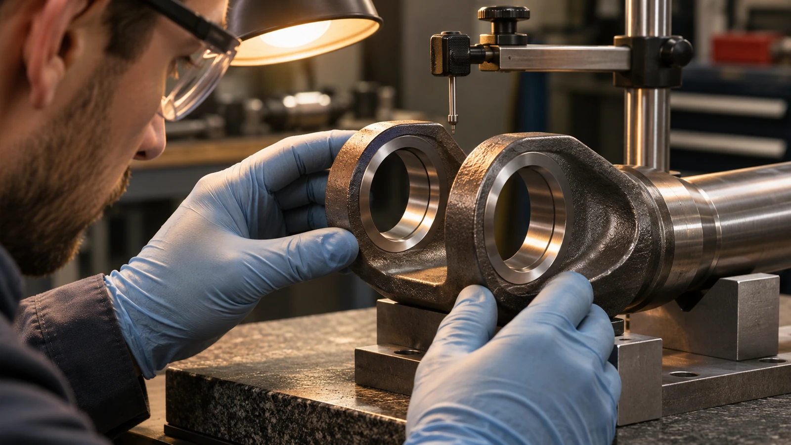
It is also useful to separate controlled features from clearance geometry. The bearing seats, spline, and flange face may directly affect fit or motion. A cast or forged exterior may simply provide stock and mass. Treating every surface as equally critical can add measurement effort without improving the connection. On the other hand, a broad “general tolerance” note cannot replace explicit control of a critical axis or position relationship.
Choose stock and route around the feature set
Production yokes may begin as forgings or other near-net shapes, while early design iterations may be machined from billet. The right choice depends on the released design, quantity, material specification, stock availability, and the features that must be validated. A billet prototype can help teams assess interfaces before tooling decisions are locked, but it does not automatically represent the grain flow, residual stress, or performance of a production forging.
Machining from billet offers direct access to geometry changes and avoids dedicated forming tooling for small development quantities. It can also remove a large volume of material and make thin ears more sensitive to distortion. A forged blank can reduce stock removal for a mature design but requires the blank, flash, allowance, and process controls to be defined. Ask the supplier to quote against the actual blank condition rather than assuming “raw material” means the same thing to every party.
Material selection must follow the drawing and program specification. Alloy steel and aluminum are both used across driveline designs, but they are not interchangeable based on a general strength comparison. Product form, heat-treatment condition, joining method, corrosion environment, and downstream finishing all matter. The site’s automotive CNC machining overview explains the broader custom-part context; the yoke drawing still governs the selected material and acceptance criteria.
Keep the machining sequence tied to the axis
Setup strategy should preserve the intended relationship between the joint features and the shaft interface. One route may establish a mounting face and a center reference first, then machine the paired ears and bearing seats from a stable datum. Another design may favor finishing the shaft-side spline or pilot before the joint end. The best order depends on access, stock geometry, clamping stiffness, and whether the blank can move as material is removed.
Long-reach tools, deep recesses, interrupted cuts, and narrow ear sections can affect surface quality and dimensional stability. If the yoke is machined from a stressed blank or a heat-treated condition, the process plan should account for how much stock is removed in each stage and when critical features are finish-cut. A shop may use intermediate inspection or a relaxed-rest sequence where the geometry warrants it, but the method should be agreed against the drawing and material state rather than promised generically.
When a yoke includes turned spline pilots, cylindrical seats, or concentric transitions, CNC milling and turning may be combined. The relevant CNC turning service page is a process reference for round interfaces; a feature that needs a particular form, spline class, or inspection method should still be called out explicitly. Avoid assuming that a nominal diameter describes a spline or bearing interface completely.
Inspect relationships, not isolated dimensions
An inspection plan should connect each measurement to a functional question. Are the bearing seats coaxial? Is their position and orientation controlled relative to the yoke’s shaft axis? Does the flange seat against its mating face without rocking? Does a spline or pilot meet the specified fit? Which surfaces need a finish measurement, and in what condition should that measurement be taken? A coordinate-measuring machine, dedicated gauge, or functional fixture may each answer different questions; the drawing and inspection plan determine the method.
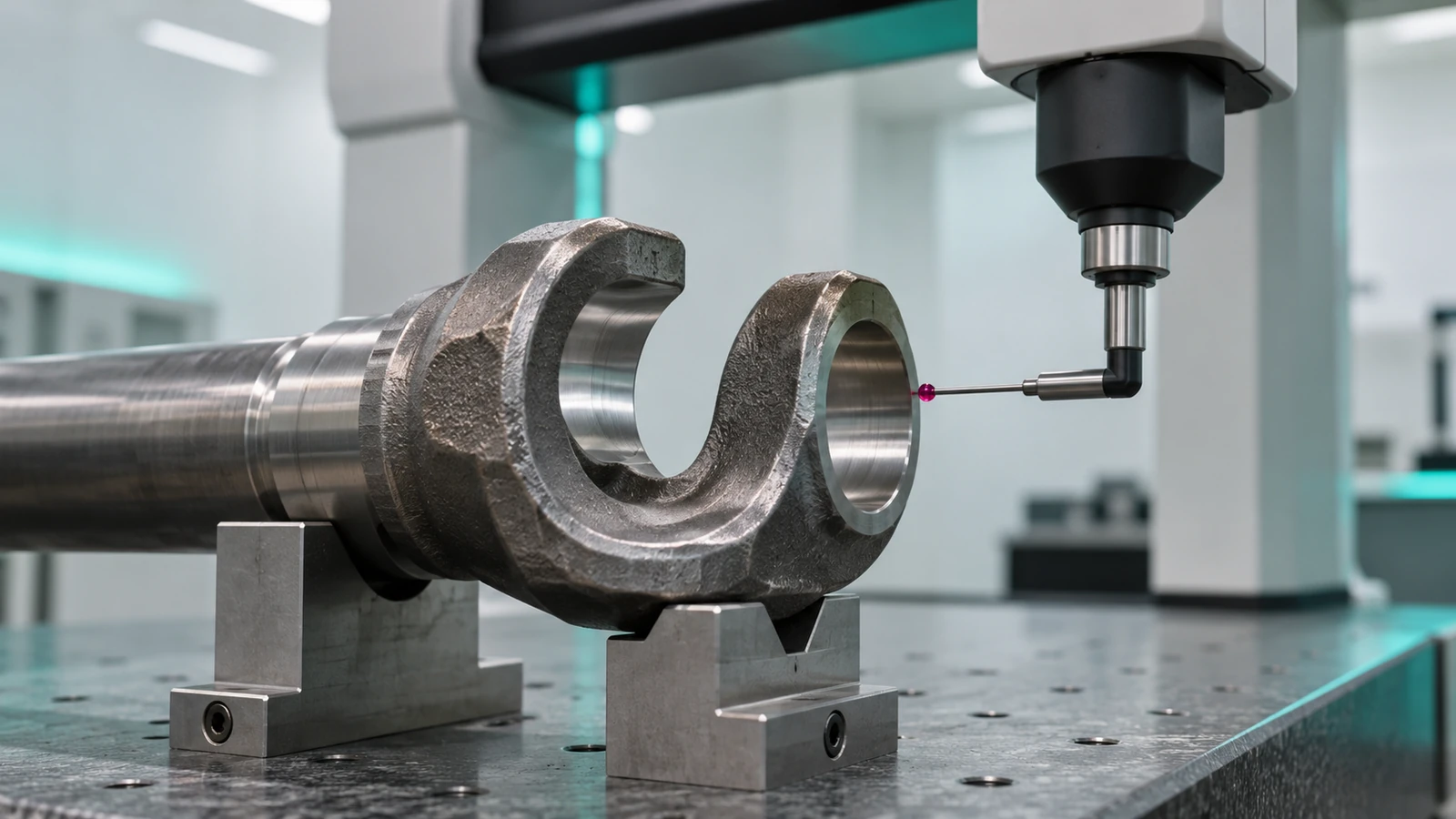
Part orientation matters. If a component is measured free-state, clamped, or assembled with a representative joint, the report should state the condition. A fixture can improve repeatability, but it must locate the same datums that define acceptance. Check the measuring probe’s access to the bottom of a bearing seat and the edges of a groove; a report that samples only accessible areas may miss a critical feature.
For a prototype, define the report scope before production. The customer and supplier can agree on a first-article dimensional report, selected critical characteristics, material documentation, and any finish or heat-treatment records. These records should identify the part revision and process stage. They are evidence of the stated checks, not proof of vehicle-level durability or qualification unless the program has separately defined those tests.
Make the quote package useful to the shop
A practical RFQ includes the controlled drawing and model, quantity, revision, material grade and condition, blank form, finish and heat-treatment requirements, critical characteristics, inspection expectations, and the prototype’s verification purpose. State whether the supplier is expected to source stock, machine from a customer-supplied blank, perform secondary operations, or return the yoke ready for a defined next step. Attach the mating interface context when it is needed to interpret datums, but keep the released part definition authoritative.
Flag changes from the previous revision: bore spacing, ear thickness, spline geometry, flange pattern, or stock allowance can alter setups and inspection. If several variants are planned, provide a family table and identify which features change. This helps a supplier distinguish common tooling and programming from variant-specific inspection instead of pricing from an ambiguous combined model.
Jucheng’s automotive prototyping service can be considered when a team needs custom components to evaluate fit or design iterations. Confirm the actual scope, material, quantity, and records for each request. A quote should state what is included and what remains with the customer, especially for heat treatment, balancing, assembly, or vehicle testing.
Frequently asked questions
Can a driveshaft yoke be machined from billet for a prototype?
It can be a practical route for a limited prototype when the drawing, material, stock, and verification goal support it. Billet machining may differ from a later forging in material flow and residual-stress behavior, so it should not be treated as a substitute for production-process qualification.
Which yoke features usually need the clearest datum definition?
The answer depends on architecture, but paired bearing seats, shaft-axis features, flange faces, splines, and pilots often form the important interface chain. The engineering drawing must identify which relationships control fit and motion.
Does a dimensional report confirm driveline balance?
No. Dimensional inspection checks specified geometry. Balance is a separate requirement with its own method, configuration, and acceptance limits. Include it in the program scope when it applies.
When yoke drawings make the interface chain, material condition, and verification purpose explicit, the machining quote becomes easier to compare and the resulting part easier to assess. That is the foundation for a useful prototype build and a controlled handoff to the next manufacturing stage.

