


Orthopedic cannulated drill machining must preserve the relationship between the internal passage, cutting features and drive interface. An external diameter can pass inspection while the bore wanders, the tip becomes asymmetric or the connection seats incorrectly. The manufacturing review therefore starts with those relationships and with the device drawing that defines how they are accepted.
Here, cannulated drill means the hollow cutting component supplied to a device or instrument manufacturer. The powered handpiece is a different assembly. Keeping that scope clear helps buyers request the correct work: machining and finishing a drawing-defined component, with evidence appropriate to its intended development or production stage. It also prevents a component quotation from being mistaken for approval of a complete surgical system.
A useful first discussion follows the broader medical device manufacturing processes from material receipt through machining, finishing and inspection. For this particular component, the difficult questions concentrate around the bore and cutting end. The design owner must define intended use and acceptance; a supplier should identify manufacturing risks without changing those requirements silently.
Three features, one reference system
Consider a drill with a central passage, fluted cutting length and a shaped drive connection. Each feature has its own dimensional requirements, but the drawing must also establish how they relate. Inspecting them in unrelated coordinate systems can hide an assembly problem. The reference used to inspect the cutting end should have an explicit connection to the reference used for the drive interface.
Begin by identifying what locates the component in the mating equipment. A cylindrical shank may locate differently from a shoulder, taper or proprietary connection. Determine whether the intended rotational reference follows that locating geometry or another defined datum. Then specify which surfaces and axes are evaluated against it. The manufacturing team should not assume that the outside diameter automatically defines every requirement.
The bore creates an additional question: is its acceptance based on size alone, straightness, location, usable clearance, or a combination? A plug passing through a hole can establish a limited functional result, but it does not provide a complete map of wall thickness or bore position. Choose the evidence that answers the actual requirement. Do not describe one successful gauge check as proof of every geometric relationship.
For a prototype, a sectioned development sample can help reveal hidden geometry, provided it is clearly identified as an engineering sample. Production inspection may use a different method or an approved sampling plan. Agree on that distinction before quoting so that a useful development investigation does not become an unplanned destructive check on deliverable parts.
Choose the bore route before the flute route
Two starting routes deserve consideration: a solid blank with a subsequently produced passage, or appropriately specified hollow stock. Neither route is universally better. Length, wall thickness, material condition, available stock, inspection access and lot size affect the choice. Hollow stock still requires confirmation of its internal geometry and traceability; a solid blank still needs a feasible plan for producing and verifying the passage.
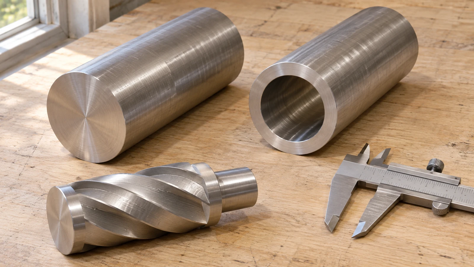
Machining a bore before completing external features can preserve a more supportive blank during drilling. It also creates a reference that later operations may need to follow. Completing the external profile first may simplify some setups, but it can leave a less rigid section for later internal work. The selected sequence should explain how alignment is preserved and how the part is supported when its stiffness changes.
Flutes remove material unevenly around the component. Their manufacture can change local stiffness and expose variation that was less obvious in the blank. Workholding, cutting engagement and intermediate checks should therefore be planned together. A fixture that grips securely can still distort a thin section; inspection after release is essential when the free-state geometry controls acceptance.
Tool entry, exit and breakthrough also deserve separate attention. A passage intersecting a cutting feature can leave an edge that is difficult to reach or inspect. Plan access for controlled edge finishing before that access disappears. The correct response is a defined process and inspection method, not a general instruction to remove all sharp edges, which could alter the cutting geometry.
Material condition changes the manufacturing plan
The material specification should identify the grade, product form and required condition. The phrase surgical stainless steel is insufficient for purchasing or process planning. Different alloy and heat-treatment choices can change machining behavior, achievable edge condition and the sequence of finishing operations. Selection belongs to the device design and its verified requirements, rather than to whichever stock is easiest to obtain.
When reviewing l'usinage de l'acier inoxydable, distinguish the condition received from the condition required at delivery. If a thermal operation occurs between roughing and finishing, establish which dimensions are left for final correction and which records accompany the lot. Do not assume a finished dimension will remain unchanged through an intervening process.
Cleaning and surface treatment also need defined boundaries. A treatment selected for corrosion performance does not replace geometric inspection or establish clinical suitability by itself. Specify protected areas, allowable changes and acceptance methods. Cutting edges, internal passages and connection features may require different handling even when they belong to the same small component.
For early development parts, the buyer should identify whether material substitutions are permitted. A substituted alloy can be useful for a clearly labeled fit study, but it cannot silently represent the cutting performance or processing behavior of the intended material. Keep sample purpose visible on the order and inspection record.
What the inspection plan needs to distinguish
A compact inspection matrix helps prevent one measurement from standing in for several different requirements. The following examples describe evidence categories, not universal acceptance limits. The released drawing and agreed inspection plan determine the actual methods and coverage.
| Exigence | Evidence to plan | Common gap |
|---|---|---|
| Internal passage | Size and applicable geometry or functional clearance checks | Assuming passage clearance proves bore location |
| Cutting end | Defined profile, symmetry and edge-condition inspection | Checking only the outside envelope |
| Drive connection | Dimensions and fit against the specified interface | Using an unidentified mating sample |
| Finished component | Required relationships in the specified datum system | Combining results from unrelated setups |

Internal burrs and residues require particular attention because an acceptable external appearance tells little about a narrow passage. Inspection access should be considered during process development. Where direct observation is limited, agree on an appropriate alternative method and its detection limits. Record what was actually checked instead of describing the component as completely verified without supporting coverage.
Keep dimensional acceptance separate from device performance validation. Component inspection can demonstrate conformity to specified characteristics. It does not automatically establish cutting performance, reprocessing performance or compatibility with every powered system. Those questions require the design owner鈥檚 relevant verification and validation activities.
Prepare an RFQ that exposes the difficult features
Send the model and drawing together, with the controlling revision identified. Include the mating connection definition, passage requirements, material and delivery condition, quantities and intended sample use. Highlight features whose inspection requires special access or a customer-specific method. If two documents disagree, resolve that disagreement before the supplier builds a process around the wrong requirement.
Jucheng Precision can review the component through its Services d'usinage CNC, with the scope agreed against the supplied drawing. A useful review identifies which features can be produced in a common setup, where separate operations are needed, and what finishing or inspection steps must be included in the quotation. Any special process or qualification requirement should be confirmed for the specific order.
For repeat orders, retain more than the final dimensions. Record the approved material condition, relevant process sequence, inspection references and revision history. A change to the blank or finishing route may deserve engineering review even when a sample still fits. This traceable handoff gives the buyer a clearer basis for comparing a prototype with the next manufacturing lot.
Questions to settle before the first sample
Does cannulation make this the same topic as a drill guide?
No. A guide locates or constrains an instrument; the cannulated drill component contains its own internal passage and cutting features. Their interface can be discussed together, but their manufacturing requirements and acceptance evidence differ.
Should every small feature receive the tightest available tolerance?
No. Assign requirements according to function and the relevant design analysis. Unnecessarily tight requirements can increase manufacturing and inspection work without improving the feature that actually controls fit.
Can a successful fit check replace the drawing?
A fit check can supplement an agreed inspection plan. Its value depends on the identity, condition and intended coverage of the mating item. It should not replace unspecified dimensional or material requirements.

