


Automotive composite materials combine reinforcement and matrix to create properties that a single material cannot provide efficiently. The attraction is often described as lightweighting, but a sound decision also considers stiffness direction, impact response, temperature, joining, moisture, finish, repair, tooling, production rate, inspection, and end-of-life strategy.
The useful question is not “Which composite is best?” It is “Which architecture creates the required behavior with a manufacturing and validation route the program can control?”
Decision map
A Composite Is an Architecture, Not a Resin Name
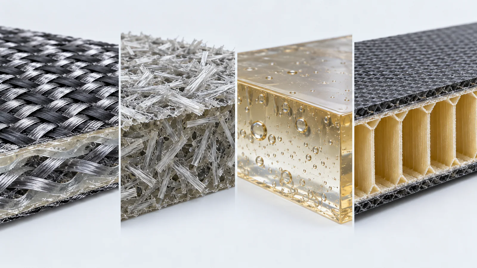
The reinforcement may be continuous carbon fiber, woven glass, chopped fiber, natural fiber, or a hybrid. The matrix may be thermoset or thermoplastic. Fiber length, orientation, volume fraction, weave, ply sequence, consolidation, porosity, and local thickness shape the result. Two parts described as “carbon fiber” can therefore behave very differently.
Begin by translating system requirements into directional loads and environmental exposures. A battery cover may prioritize flame management, sealing, impact, and broad-panel stiffness. A seat structure may prioritize fatigue and crash load paths. A decorative interior panel may prioritize surface quality, mass, touch, and low emissions. The material architecture must follow the job.
Within the larger fabrication automobile cluster, composites should connect to the metal, plastic, prototype, tooling, finishing, and assembly choices around them. Treating the composite as an isolated material misses the interfaces that usually determine program risk.
Design Backward From the Failure You Cannot Accept
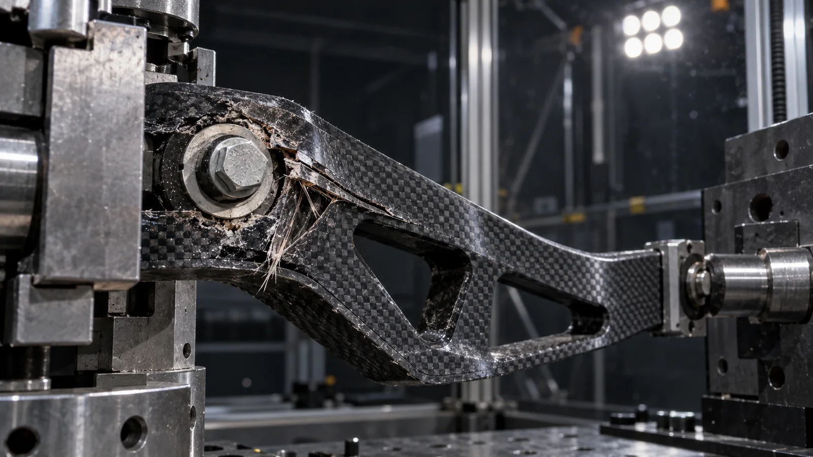
Metals are often approximated as isotropic for early design. Many composites are strongly directional. A laminate may be stiff along a fiber direction while remaining vulnerable to through-thickness load, bearing stress, edge damage, or delamination. Loads entering through bolts, clips, inserts, adhesive edges, and impact points need explicit paths.
Start with forbidden outcomes: loss of containment, visible surface fracture, fastener pull-through, loss of alignment, water ingress, electrical isolation failure, or an unsafe fragment. Then map the initiating mechanisms. This approach produces clearer design actions than selecting a high headline tensile strength and hoping it controls every mode.
A composite part is efficient only when its fibers, geometry, joints, and manufacturing variation all support the same load path.
Edge distance, holes, cutouts, tight radii, thickness transitions, and ply drops deserve special attention. Local reinforcement can solve one issue while creating resin-rich zones or difficult consolidation. Use finite-element analysis as a guide, then correlate it with representative coupons and subcomponents.
Manufacturing Route Changes the Material You Actually Get
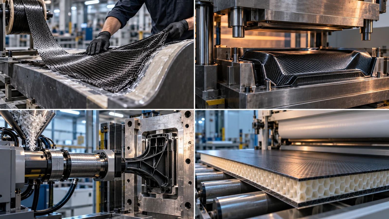
| Family | Typical strength | Program concern |
|---|---|---|
| Continuous-fiber laminate | High directional efficiency and tailored stiffness | Layup control, consolidation, cycle time and inspection |
| Compression-molded compound | Complex shapes and scalable automotive cycles | Flow-induced orientation and local property variation |
| Fiber-reinforced injection molding | Integrated features and high production efficiency | Fiber orientation, weld lines, warpage and surface |
| Sandwich construction | High panel stiffness at low mass | Edge closure, inserts, moisture and local crush |
A manufacturing specification should therefore name more than the base polymer and fiber. It should control reinforcement form, orientation or layup, local thickness, cure or consolidation state, permissible defects, trimmed-edge requirements, and traceability. Those controls connect the drawing to the process.
Tooling also affects feasibility. Thermal expansion, cure temperature, pressure, surface finish, expected cycles, part size, and dimensional target influence whether a tool should be machined metal, composite, polymer, or a hybrid. Prototype tooling can accelerate learning, but production decisions should reflect the full cycle and maintenance plan.
Most Composite Problems Appear at Hybrid Interfaces
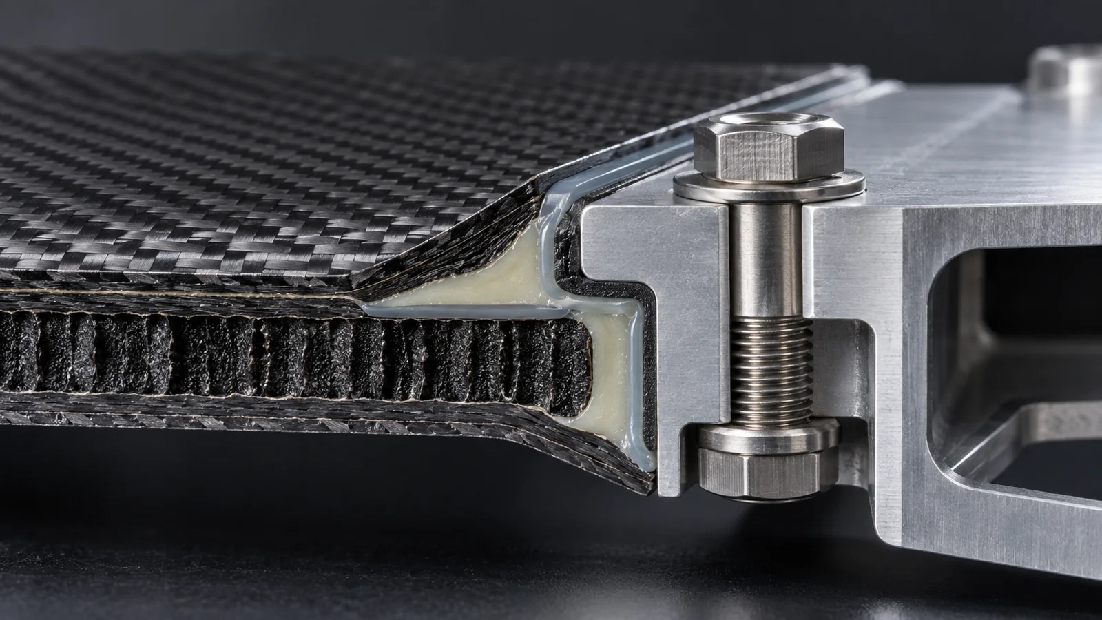
Automotive assemblies rarely consist of one material. Composites meet aluminum, steel, copper, glass, elastomers, adhesives, foam, and molded thermoplastics. Differences in stiffness and thermal expansion concentrate load near the boundary. Galvanic isolation may be required where carbon fiber approaches certain metals in the presence of moisture.
Bolted joints need bearing area and controlled clamp load. Molded or bonded inserts need pull-out and torque resistance without creating a hard point that initiates cracking. Adhesive joints need suitable overlap, bond-line thickness, surface preparation, cure control, and peel management. A mixed joining strategy may combine adhesive load distribution with mechanical retention.
Prototype the joint as a system. A coupon can screen surface preparation and adhesive, but a subcomponent is needed to reproduce curvature, edge distance, fastener sequence, and environmental movement. CNC-machined inserts and locators from the automotive CNC machining route can provide controlled interfaces while composite geometry is still evolving.
Prototype the Risk, Not Just the Shape
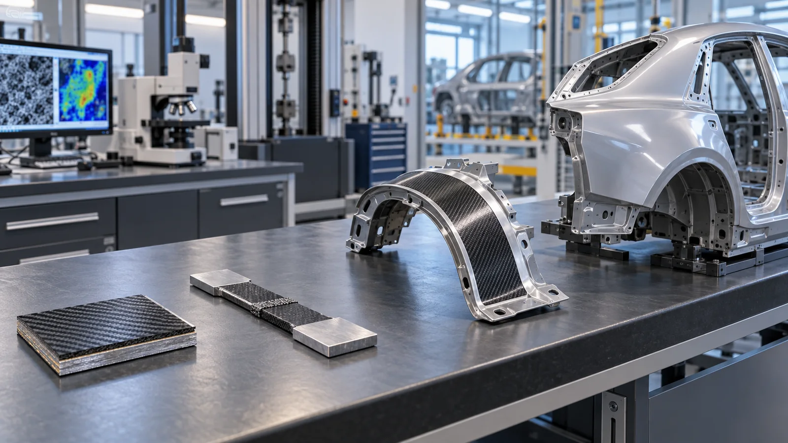
A printed visual model can validate package and access, but it does not reproduce laminate failure. A machined plate can confirm hole patterns and assembly, but it may not show delamination or bearing behavior. A hand-laid part can reveal handling and surface issues, while its fiber control and void content may differ from production.
Build the validation ladder deliberately. First isolate geometry questions. Next use material coupons for environmental exposure and joining screens. Then test subcomponents containing holes, edges, inserts, thickness transitions, and representative curvature. Finally, validate production-intent parts made with controlled tooling and process parameters.
This staged approach is compatible with automotive rapid prototyping, provided every stage states what remains unproven. Fast iteration is valuable; false equivalence between a prototype material and the production composite is not.
Inspection Must Be Linked to a Defect Mechanism
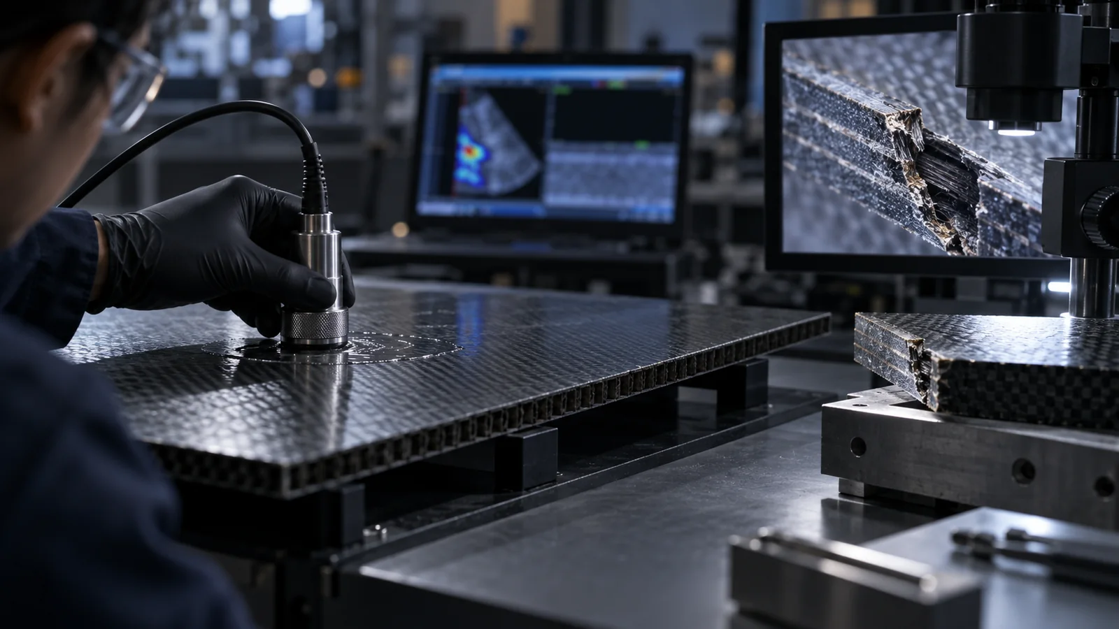
Visual inspection can find surface cracks, resin-rich areas, exposed fibers, wrinkles, edge damage, and finish defects. Dimensional inspection controls datums, trim, holes, interfaces, and assembly position. Tap testing, ultrasound, thermography, radiography, or other nondestructive methods may be selected for internal features according to material, thickness, geometry, and criticality.
Not every indication is equally harmful. Acceptance criteria should relate defect type, size, location, and load path. A cosmetic surface mark and an internal delamination near a fastener should not share one generic limit. Reference standards can support the method, but the product risk should determine the acceptance plan.
Repair must be designed into the program rather than improvised after damage. Define whether a component is repairable, which zones allow repair, what preparation and cure are required, and how the repair is inspected. Service access and traceability matter when components remain in the vehicle for many years.
Frequently Asked Questions

Are automotive composites always lighter than metal?
No. Weight benefit depends on load path, geometry, safety factors, joints, inserts, coatings, manufacturing variation, and the metal design used for comparison. A poorly integrated composite can add local reinforcement and hardware until the expected advantage disappears.
Can composite automotive parts be CNC machined?
Many can be trimmed, drilled, milled, or finished by CNC equipment, but tooling, dust control, edge support, heat generation, and delamination risk require process-specific planning. Machining can expose fibers, so sealing and cosmetic requirements should be defined.
Which is better for automotive parts: thermoset or thermoplastic composites?
Neither is universally better. Thermosets may offer established high-performance laminate routes, while thermoplastics can support faster forming, welding, impact toughness, and recycling options. Temperature, rate, geometry, joining, finish, and lifecycle goals determine the choice.
What should a composite-part RFQ include?
Include geometry, load cases, environmental conditions, target quantity, reinforcement and matrix requirements or performance targets, surface class, critical interfaces, permissible defect criteria, inspection expectations, joining details, validation stage, and tooling-life assumptions.

