


Automotive assembly fixtures hold, locate, support, and sometimes sequence components while an operator or automated station joins them. Their real purpose is not to make the part immovable. It is to constrain the correct degrees of freedom, preserve functional datums, expose the work area, and produce a repeatable assembly without damaging the components.
A good fixture turns a tolerance and workflow problem into a controlled physical setup. A bad fixture hides variation until the completed subassembly reaches inspection.
Fixture design review
Begin With the Assembly Output, Not a Fixture Concept
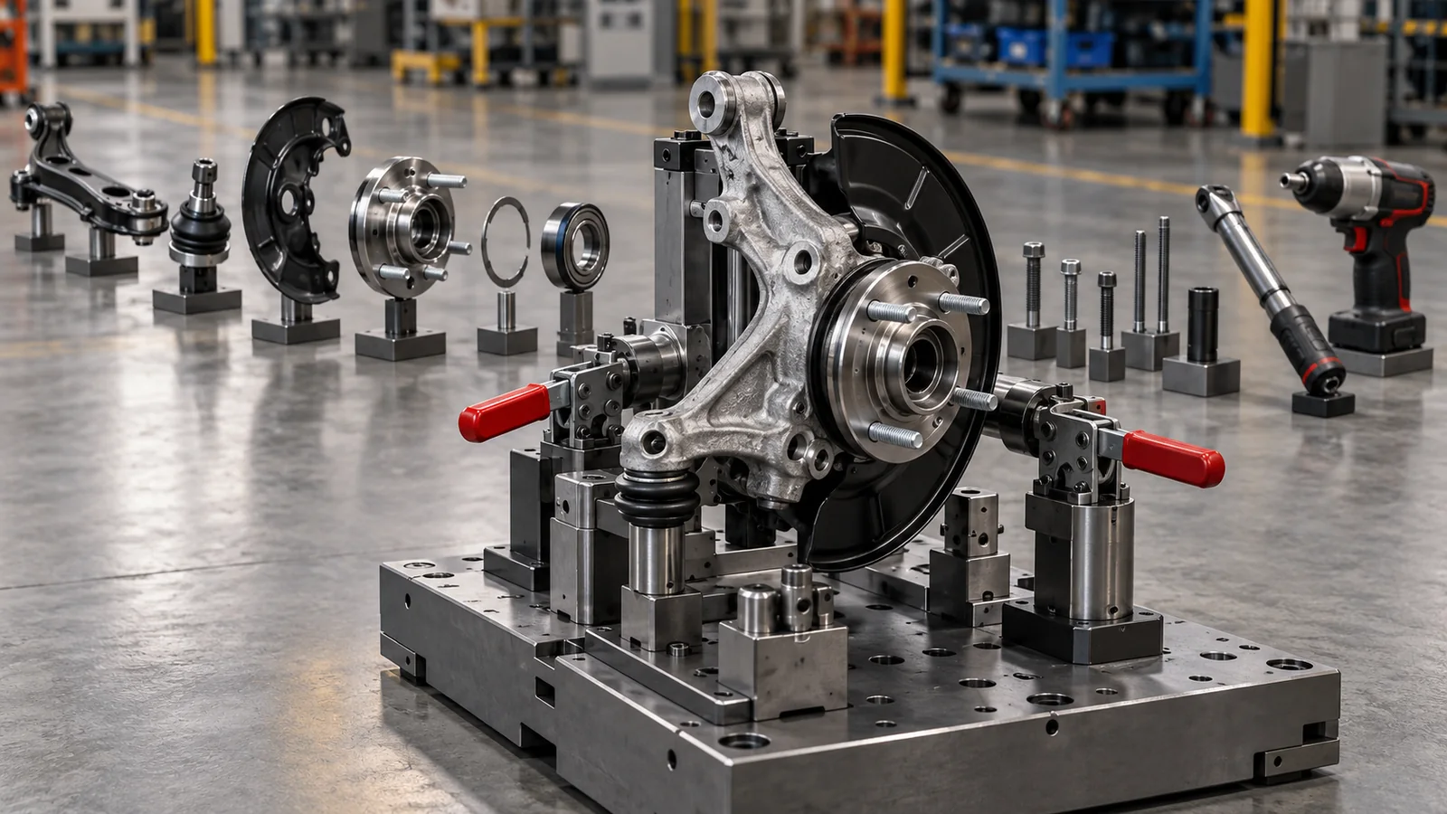
Define what leaves the station: a clipped interior module, bonded enclosure, welded bracket set, fastened housing, cable-equipped mechanism, or aligned body component. Identify the features that must be controlled after joining, not only the individual part dimensions before joining.
List the joining process and its disturbances. Welding introduces heat and shrinkage. Pressing creates reaction force. Adhesive bonding needs bond-line control and cure time. Fastening introduces torque and sequence effects. Ultrasonic welding requires support near the energy path. The fixture must resist or accommodate those effects.
Connect the work to the parent fabrication automobile plan, then link it to the closest subassembly process. That hierarchy keeps fixture content focused on production control rather than turning it into another generic automotive-process article.
Convert the Datum Scheme Into a Constraint Plan
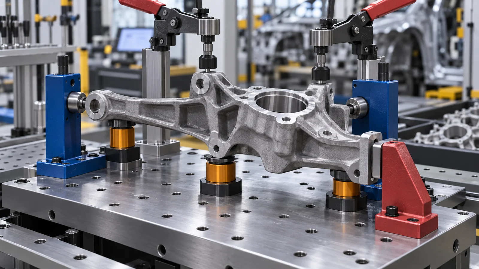
The familiar 3-2-1 concept constrains six degrees of freedom, but real automotive parts are not perfect blocks. Thin sheet metal, molded plastics, castings, foams, seals, and decorative surfaces can deform under clamp load. Locators should contact stable functional features whenever possible.
Map the primary, secondary, and tertiary relationships from the assembled product. Then decide which locators are fixed, which float, which are adjustable, and which allow thermal or part-to-part variation. Over-constraining a flexible component can force it into the fixture while producing a stressed assembly that springs out afterward.
Use relieved pins, diamond pins, nests, rest pads, edge locators, vacuum, magnets, or compliant elements according to the geometry. Control wear surfaces and make replaceable details accessible. The datum transfer should be clear enough that maintenance can restore the fixture without a full redesign.
The Fixture Must Fit the Process and the Person
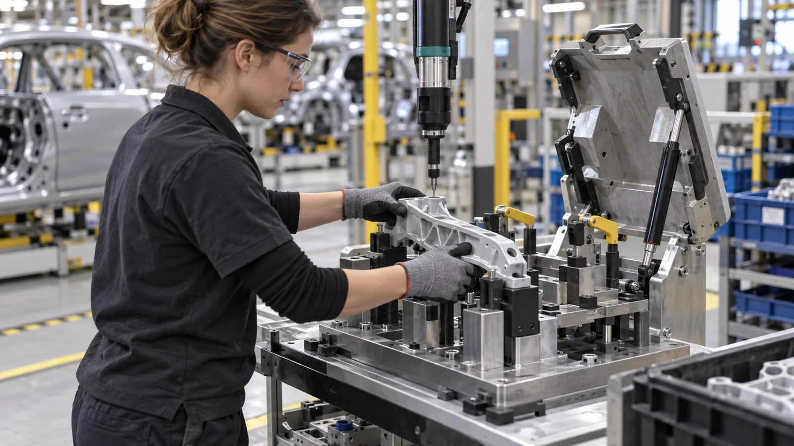
Provide access for hands, robots, welding guns, drivers, adhesive dispensers, inspection probes, and part removal. Check approach angles and tool envelopes using real equipment data. A fixture that locates perfectly but blocks the fastening tool has failed its main job.
Sequence matters. The operator should not need to reach across sharp edges, hold a loose component while closing a clamp, or remember an invisible orientation. Loading should move from stable location to secure clamping with clear feedback. Unloading should not twist clips, seals, or freshly bonded joints.
Review ergonomics for the actual part mass, repetition, gloves, line height, and changeover. Handles, lift assists, balanced lids, accessible clamps, and visual status indicators reduce variability as well as strain. Automation requires the same discipline: robot clearance, gripper access, sensor fields, cable routing, and recovery after a fault.
Choose Fixture Materials by Duty Cycle and Contact Risk
| Fixture element | Useful material route | Design concern |
|---|---|---|
| Base and structural frame | Machined aluminum or welded/machined steel | Stiffness, transport, thermal stability and access |
| Precision locators | Hardened steel, tool steel, stainless steel | Wear, corrosion, replaceability and calibration |
| Protective nests | Engineering polymer, urethane or coated metal | Surface marking, creep, contamination and life |
| Rapid-change details | CNC or additive manufactured modules | Datum repeatability and retention |
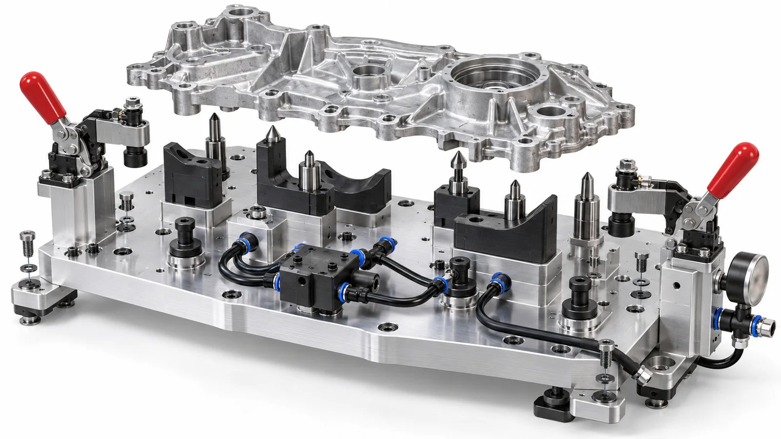
Automotive CNC machining supports accurate bases, locators, pin blocks, nests, and replacement details. Additive manufacturing can create lightweight ergonomic nests, conformal support, vacuum passages, and quickly revised modules. Combining both often provides better economics than forcing one process across the entire fixture.
Error Proofing Should Detect the Wrong State Early
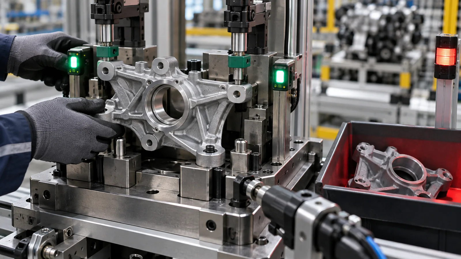
Poka-yoke features can physically prevent an incorrect part or orientation from loading. Sensors can confirm presence, seating, clamp position, fastener completion, component identity, or adhesive application. The design should distinguish “something is present” from “the correct component is fully seated.”
Choose the verification point before irreversible joining. A missing clip discovered after adhesive cure or a wrong bracket discovered after welding creates expensive rework. Where traceability matters, connect the fixture or station result to part identification and process records.
Visual controls remain useful. Color-coded change parts, engraved positions, protected setup masters, and clear home states help technicians restore the correct configuration. Error proofing should simplify work rather than bury the operator under alarms that do not identify the fault.
Commission the Fixture With Real Part Variation
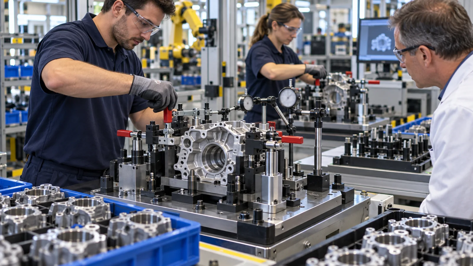
Do not prove the fixture using one ideal component. Run parts near relevant tolerance limits, multiple cavities or tools, different lots, and representative cosmetic conditions. Confirm that loading remains possible without forcing and that the released assembly meets its functional dimensions.
Use a fixture capability study appropriate to the measured result. Repeat loading by different operators where manual handling contributes variation. Separate measurement-system variation from assembly-process variation; otherwise the fixture may be adjusted to compensate for an unstable gauge.
Document the setup, master or calibration method, replaceable wear parts, preventive-maintenance frequency, torque settings, sensor checks, and reaction plan. Connect the completed fixture to automotive subassembly requirements so ownership does not end when the hardware ships.
Jucheng Precision can coordinate fixture design with CNC machining, additive manufacturing, sheet-metal fabrication, finishing, inspection, and trial assembly. This allows fixture decisions to be tested against real components instead of idealized nominal models.
Frequently Asked Questions
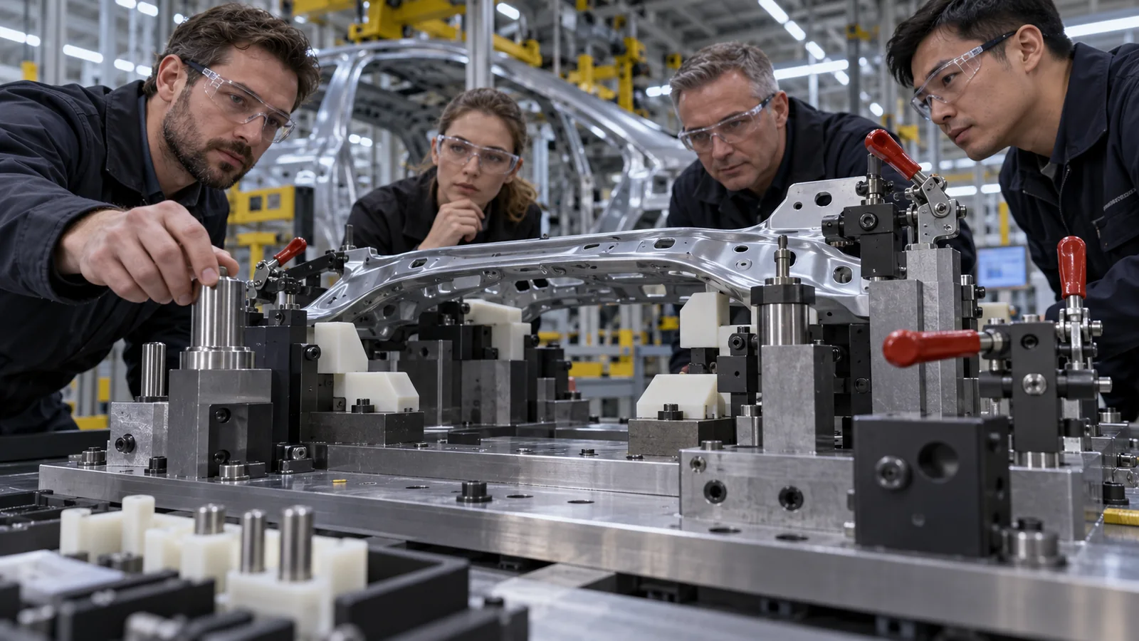
What is the difference between an assembly fixture and a checking fixture?
An assembly fixture positions and supports components while work is performed. A checking fixture evaluates whether a part or assembly meets defined dimensional or functional conditions. Some stations combine both functions, but their measurement capability must be validated separately.
Can automotive assembly fixtures be 3D printed?
Yes, especially nests, handles, guides, vacuum features, sensor mounts, and low-volume modules. Precision wear locators and heavily loaded structures may still require machined metal. Hybrid construction lets each material perform the duty it handles best.
How are flexible plastic or sheet-metal parts located?
Use stable functional regions, distribute support, limit clamp force, and allow intended float. The design should reproduce the assembled condition without forcing the component into an artificial shape that changes after release.
What data is needed to quote a fixture?
Provide component and assembly CAD, datum and critical-feature drawings, joining method, cycle target, loading sequence, equipment envelopes, expected variants, production volume, operator or robot information, verification needs, traceability, and preferred acceptance procedure.

