


A parking pawl is a small part with a very specific job: it engages a toothed parking gear to restrain transmission output when Park is selected. For a designer or prototype buyer, the useful question is not simply whether the pawl looks right. The drawing must make the pivot, engagement face, release clearance, and surrounding datums understandable as one mechanism. A transmission parking pawl can be machined to its nominal outline and still be difficult to evaluate if those relationships are left implicit.
This guide focuses on drawing review and prototype planning. It is not a vehicle repair procedure, a universal tooth-design specification, or an approval of a production mechanism. Parking-lock geometry varies by transmission architecture. Use the responsible design authority’s dimensions, material callouts, heat-treatment requirements, and validation plan.
Start with the engagement relationship, not the outside profile
The functional chain normally includes a pawl, a pivot or support, a spring or actuator linkage, and a parking gear. The pawl tip approaches the gear teeth as the selector moves into Park. The shape and position of the contact surfaces influence whether the mechanism reaches the intended engaged position, how it is retained, and how it releases. A transmission parking pawl drawing should therefore identify the engagement face and its relation to the pivot axis and any actuator-contact feature.
Do not infer a universal engagement angle from a generic illustration. A patent may illustrate one mechanism, while a service manual describes a particular transmission family. The drawing owner must define the controlled geometry for the actual design. For context, technical literature on parking-lock mechanisms discusses contact position and tooth interaction as design variables, but it does not replace a model-specific specification.
Choose datums that follow how the pawl is located
Datum selection should represent the way the part is constrained in the assembly. If a pivot bore or pivot surface locates the pawl, it is often the natural starting datum feature. The engagement face can then be controlled relative to that pivot and to a side face that establishes lateral position. If the assembly uses a separate pin, bracket, or shoulder, the drawing should clarify which feature establishes the actual axis and which features merely retain the part.
For a prototype, a practical datum scheme helps the machinist fixture the blank and helps the inspector reproduce the design intent. It also reduces a common review problem: reporting a bore diameter and a tooth-face dimension separately without stating their relationship. That relationship is the purpose of geometric controls and basic dimensions on the released drawing, where applicable.
Consider a hypothetical design review in which the pivot hole is dimensioned from one edge while the pawl tip is dimensioned from an unrelated edge. The part may satisfy both linear dimensions, yet accumulated variation can shift the engagement face relative to the pivot. A better review asks which surfaces jointly define the pawl’s position when it rotates, then places the controlling dimensions and tolerances around that functional frame.
Separate contact geometry from clearance geometry
The engagement face and the nearby relief surfaces do different jobs. The working face participates in the contact with the parking gear; relief and side surfaces provide room for movement and help avoid unintended interference. Treating all of these surfaces as one general profile tolerance can hide the features that matter most. Identify which surfaces are functional, which are clearance features, and which are only for mass or packaging.
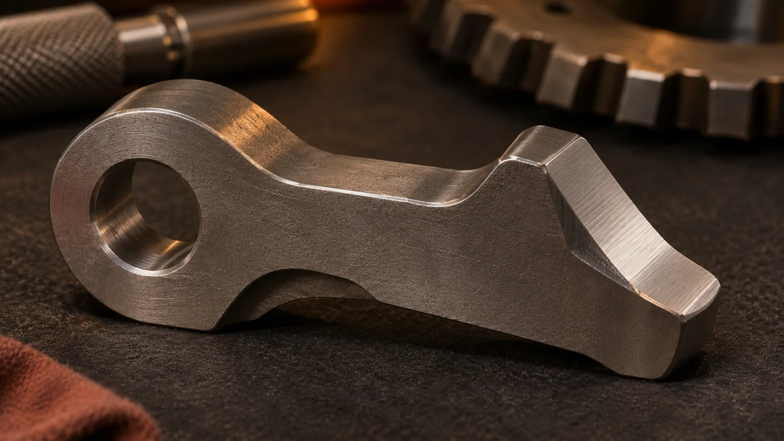
When reviewing the CAD model, rotate the pawl through the intended motion envelope and examine its approach to the gear. Look for potential interference at the tip, side faces, pivot region, and actuator contact. This is a design review activity, not a substitute for mechanism testing. The model should include the mating components or controlled reference geometry where available; a pawl-only model cannot prove a complete assembly relationship.
A transmission parking pawl may also include a spring pocket, cross-hole, retaining feature, or actuator ramp. These features can affect tool access, burr control, and inspection. Call out edge conditions only where the design requires them. Avoid blanket edge-break notes that could unintentionally change the engagement face or reduce a controlled contact area.
Plan the machining sequence around stable references
For a prototype blank, the process plan should preserve the reference features needed for later operations. A typical planning discussion might begin by establishing a stable base and side reference, then machining the pivot feature and critical faces in an order that keeps their relationship inspectable. The exact operation sequence depends on the part envelope, material, stock condition, and specified tolerances; it cannot be determined from the component name alone.
Thin arms, open slots, and localized cross-holes can make clamping and tool access more important than the apparent simplicity of the outline. Discuss how the part will be supported while the engagement profile is cut. If a feature is accessible only after a setup change, identify the datum transfer and how the setup will be checked. For prototype work, a review of the 3D model, a 2D drawing, the material specification, and the intended inspection characteristics is more useful than asking for a nominal quote from a part name alone.
Where the design calls for a hardened condition or surface treatment, confirm whether machining is intended before or after that operation and who owns the final finishing step. Do not assume a material grade, heat treatment, hardness, or coating from other pawl designs. These requirements affect the process plan and must come from the released specification.
Make inspection answer the functional questions
Inspection should cover the pivot feature, the engagement face relative to the pivot, relevant side-to-side location, and any actuator-contact feature that controls the motion. A pin or plug gauge can check a feature size, but it does not automatically verify axis location, orientation, or the engagement surface’s position. Select a measurement method that can evaluate the drawing requirement in its stated datum reference frame.
For a one-off prototype, agree in advance on which characteristics are critical and what report format is needed. If an assembly gauge is used, state what it verifies and what it does not. Preserve part identity, drawing revision, and inspection setup so that a later design iteration can be compared on the same basis. Do not label a prototype inspection as vehicle validation or durability evidence.
Engineering references and service documents can help explain the mechanism, but each serves a different purpose. A patent may show a design concept; a service manual may show how one unit is assembled or inspected. Neither automatically supplies the correct dimensions for another transmission. The source should support the explanation, while the customer’s drawing controls the part.
Prepare a useful prototype request
When requesting a machining review, provide the released drawing or a clearly marked preliminary drawing, the 3D model, material and condition, quantity, surface-finish requirements, and any post-processing scope. Flag the engagement face, pivot feature, datum scheme, and any inspection report requirements. If the model is still changing, mark the revision and list the open decisions instead of presenting an unapproved dimension as final.
For projects that need CNC milling, turning, or prototype coordination, the verified CNC machining capabilities page explains the relevant service scope. The actual process and material for a parking-lock component still need to be assessed against the drawing; this guide does not claim a specific automotive qualification or production approval.
Common drawing-review misses
- Defining the pivot bore size but not its axis relationship to the engagement face.
- Using an outside edge as a datum even though the assembled mechanism locates from a pin or support.
- Applying an edge-break note to the working face without stating an allowed condition.
- Leaving material condition, heat treatment, or coating responsibility ambiguous.
- Requesting a gauge check without stating which characteristics the gauge evaluates.
- Using a generic service illustration as a substitute for the current released drawing.
Frequently asked questions
What is the most important feature on a transmission parking pawl drawing?
There is no single feature for every design. The pivot-to-engagement relationship is often central to the mechanism, but the released design may also control actuator contact, lateral location, or retention features. Follow the drawing’s functional datum scheme.
Can the pawl profile be inspected with a simple outline check?
An outline check can be useful for selected profile characteristics, but it may not establish the location and orientation of the engagement face relative to the pivot. Use the specified datum references and an agreed measurement method.
Does this guide specify a material or hardness?
No. Material, heat treatment, hardness, and surface condition are design-specific. They must be stated by the responsible engineering authority and confirmed on the drawing or purchase specification.
Can a prototype prove parking-system durability?
A machined prototype can support dimensional review and fit evaluation. Durability or vehicle-level validation requires a separate engineering test plan and acceptance criteria.
Sources and scope
For mechanism context, see the published parking-lock mechanism patent and the model-specific descriptions in transmission service literature. These sources illustrate design and service context; they do not establish requirements for a different transmission. Dimensions, tolerances, materials, and validation criteria must come from the approved design documents.

