


Robotics Manufacturing Pros and Cons: 5-Axis CNC vs. 3D Printing vs. Rapid Molding
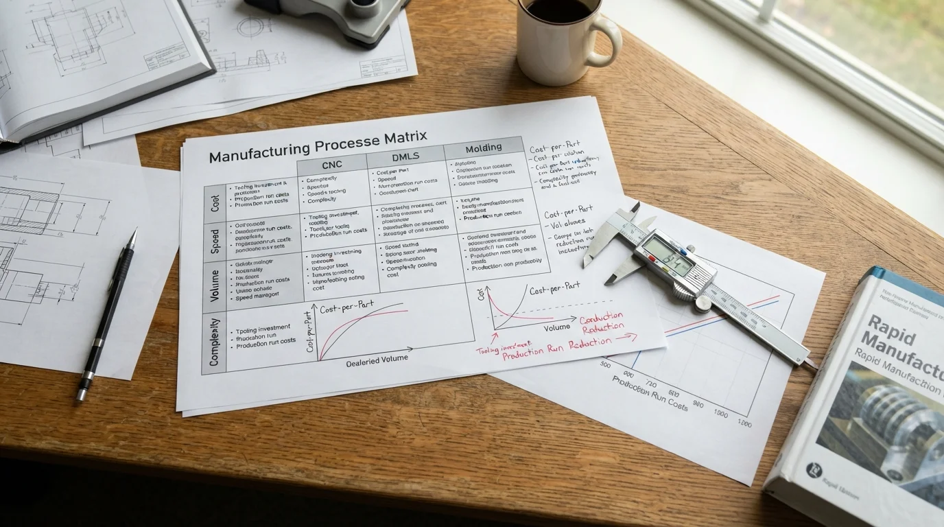
What are the pros and cons of different robotics manufacturing methods? Five-axis CNC machining delivers unmatched structural rigidity, sub-micron tolerances (±0.005 mm), and authentic forged metal grain density, but generates high buy-to-fly material scrap; Direct Metal Laser Sintering (DMLS) 3D printing enables extreme organic topology lightweighting and integrated internal channels, but suffers from high unit costs and rough as-built surfaces; while rapid injection molding provides the lowest per-piece price for exterior protective covers at scale, but demands upfront tooling CapEx. Conducting an objective evaluation of robotics manufacturing pros and cons ensures that mechatronic engineering teams select the most cost-effective and structurally sound process mix for their specific hardware architectures.
Balancing structural stiffness against production speed dictates whether an articulated automation project stays within its development runway. Understanding how subtractive cutting, additive sintering, and bridge molding interact allows development teams to build functional test articles quickly without sacrificing dimensional accuracy.
5-Axis CNC Machining: Unmatched Rigidity vs. Buy-to-Fly Scrap Waste
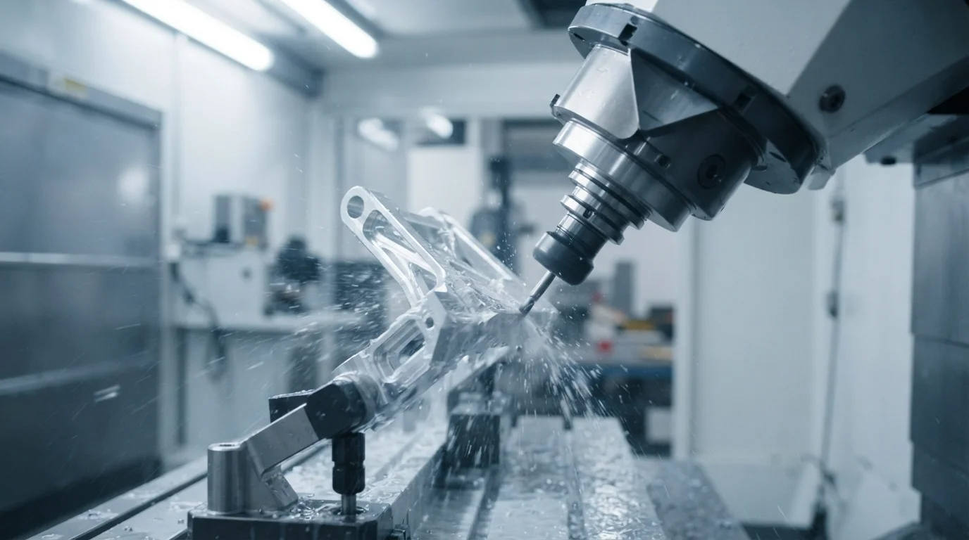
Machining structural robotic arm links and harmonic drive housings from solid billet stock guarantees 100% isotropic material density and zero internal micro-porosity. High-rigidity usinage CNC 5 axes centers cut complex compound angles and deep bearing journals in a single setup, eliminating cumulative fixture re-clamping misalignment. However, carving deep weight-reduction pockets often cuts away up to 80% of the raw metal block as scrap chips, driving up material costs on large titanium or alloy steel weldments.
Key considerations when selecting CNC machining for robotic mechanisms include:
- Sub-micron dimensional accuracy: Fine jig boring holds bearing bore concentricity to ±0.005 mm (ISO H6 class), preventing joint backlash.
- Genuine aerospace alloys: Machines high-strength AL7075-T6 aluminum and pre-toughened 42CrMo4 steel without compromising mechanical properties.
- High toolroom machine hours: Deep pocketing with small-diameter endmills extends cycle times, leading to elevated unit costs during low-volume prototyping.
DMLS Metal Additive: Bionic Lightweighting vs. Surface Roughness
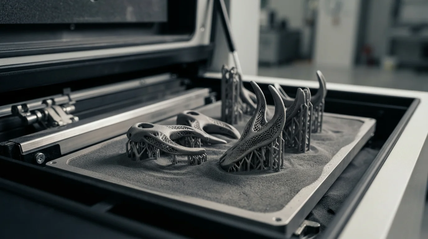
Direct metal laser sintering fuses fine metal powder layer by layer, enabling complex organic lattice structures and internal pneumatic conduits impossible to cut via line-of-sight tools. When automation engineers analyze conflicting robotics manufacturing pros and cons, additive manufacturing offers unbeatable mass reduction for dexterous bionic hands and wrist gimbals. However, as-printed parts feature rough surface finishes (Ra 6.3–12.5 µm) that require secondary machining on bearing interfaces, and unit costs remain high for large batch sizes. Discussions across robotics hardware communities on Reddit and Facebook emphasize that additive titanium is ideal for complex end-of-arm tooling but cost-prohibitive for large chassis frames.
Comparing primary manufacturing routes highlights distinct mechanical and economic envelopes:
| Méthode de fabrication | Core Advantages (Pros) | Primary Limitations (Cons) |
|---|---|---|
| Fraisage CNC 5 axes | Sub-micron tolerances (±0.005 mm), maximum rigidity, no upfront mold NRE | High buy-to-fly scrap waste, higher unit cost at large production volumes |
| DMLS 3D Printing | Organic bionic lattice structures, zero tooling setup, integrated internal channels | Rough as-built surface finish, high per-unit powder cost, slower build cycle times |
| Rapid Bridge Tooling | Lowest per-piece cost for plastic shells, fast cycle times (seconds per part) | Upfront mold tooling investment, line-of-sight draft angle restrictions |
Rapid Tooling and Molding: Low Unit Costs vs. Upfront Tooling CapEx
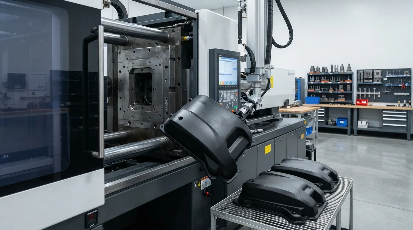
Protective arm covers, teach pendant casings, and AGV mobile base bumpers require tough, lightweight engineering polymers that resist shop-floor impacts. Sourcing these large housings via CNC billet milling or 3D printing results in unsustainable piece-part costs when batch quantities exceed 100 units. Utilizing l'outillage rapide with soft aluminum or pre-hardened steel mold inserts bridges this gap, cutting initial mold outlays by 50% while producing parts in engineering ABS ou polyurethane (PU) in seconds per press shot.
Finding the Optimal Hybrid Manufacturing Mix for Your Robot
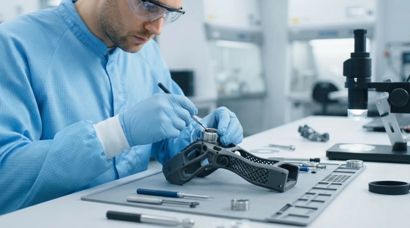
Sophisticated mechatronic assemblies rarely rely on a single production process. The most cost-effective robotic platforms combine complementary manufacturing methods into a unified build workflow:
- Joint actuators & gearboxes: 5-axis CNC machining from solid alloy steel and aluminum for zero backlash.
- Mobile chassis & battery boxes: Laser-cut and robotic-welded sheet metal for high-rigidity structural support.
- Bionic end-effectors: DMLS titanium (Ti-6Al-4V) 3D printing with secondary CNC machining for precision pin pivots.
- Protective exterior cowlings: Rapid bridge injection molding or reaction injection molding (RIM) for low-cost cosmetic shells.
Design Guidelines and Tolerance Maintenance for Multi-Process Assemblies
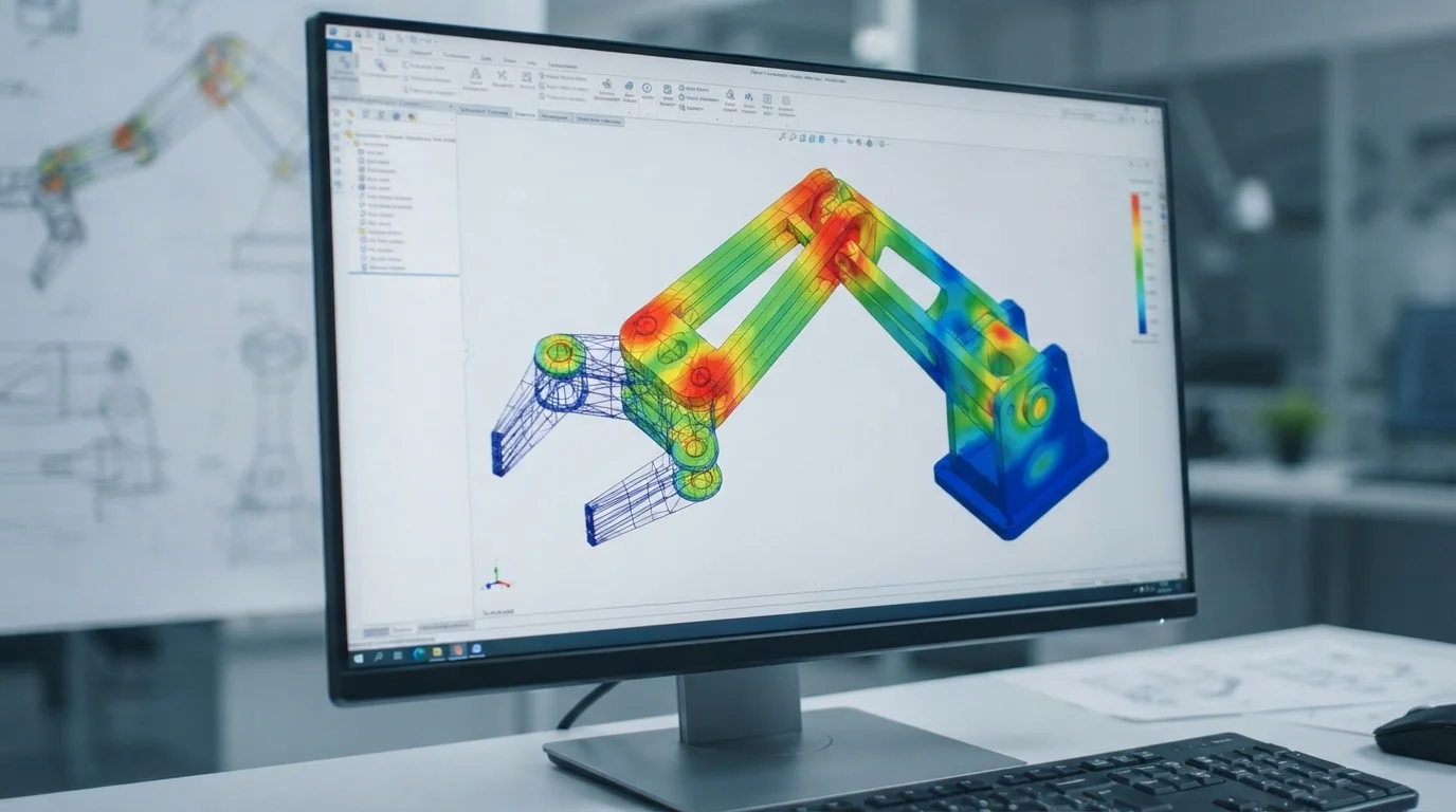
Integrating printed, machined, and molded parts into a cohesive robotic assembly requires careful datum planning and joint clearance management to prevent tolerance stack-up errors.
Key multi-process integration protocols include:
- Machined mounting pads on printed parts: Add 1.0 mm machining stock onto DMLS printed brackets so bearing journals can be finish-bored on a 5-axis mill.
- Flexible clearance on molded covers: Design 1.5 mm clearance around CNC structural links to absorb minor mold shrinkage variance without rubbing.
- Wear-resistant polymer bushings: Seat self-lubricating PEEK or Delrin sleeves inside joint pivots to prevent aluminum-on-steel galling.
Foire aux questions (FAQ)
1. When should CNC machining be chosen over metal 3D printing for robot parts?
CNC machining is preferred for primary structural links and bearing housings requiring 100% isotropic density, sub-micron concentricity (±0.005 mm), and smooth bearing surface finishes.
2. What are the main limitations of DMLS 3D printing for robotic arms?
DMLS 3D printing has higher unit costs at scale, slower build speeds, and rough as-printed surface finishes that require secondary CNC machining on bearing fits and threaded holes.
3. Why is rapid tooling ideal for robotic protective covers during pilot runs?
Rapid tooling cuts upfront mold costs by 40% to 60% compared to production steel dies, delivering authentic molded plastic shells in 2 to 3 weeks for batches between 100 and 1,000 units.
4. How does hybrid manufacturing reduce robotic gripper weight?
Hybrid manufacturing combines DMLS additive printing for hollow organic finger structures with secondary CNC finish-milling of precision pivot joints, slashing mass while maintaining fit.
5. What causes high scrap rates during CNC machining of robotic links?
Hollowing out deep thin-walled pockets from solid metal billet removes up to 80% of the raw alloy block as scrap chips, increasing raw material costs.
6. How does Jucheng Precision help robotics OEMs optimize process selection?
Jucheng Precision provides 24-hour free DFM reviews, multi-process manufacturing (5-axis CNC, sheet metal, DMLS, rapid tooling), and Zeiss CMM quality verification under ISO 9001 systems.
Why Choose JUCHENG for Your Robotics Sourcing
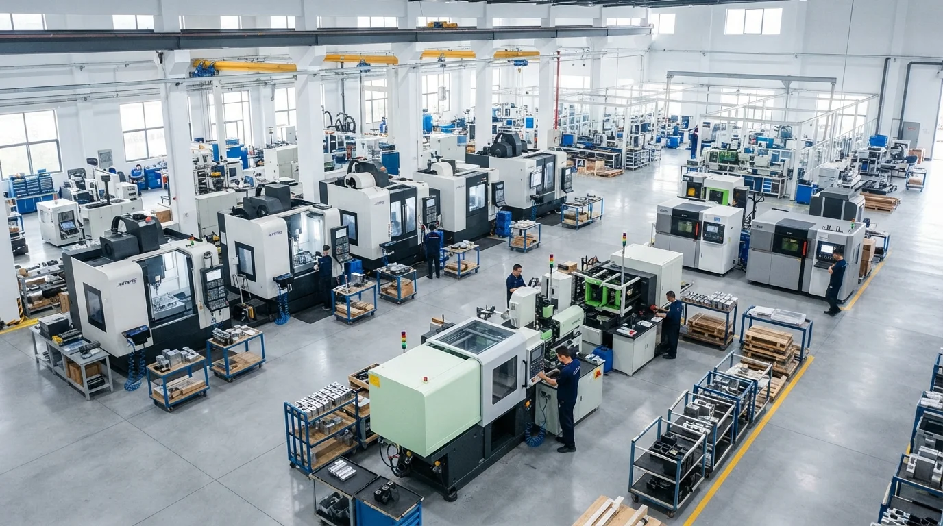
Achieving budget predictability and micro-precision kinetic performance requires an experienced manufacturing partner with multi-process infrastructure under one roof. JUCHENG supports robotics innovators by delivering comprehensive analyses DFM gratuites 24h/24 reviews that analyze tool clearances, pocketing depths, and bearing fit tolerances prior to cutting metal. Founded in Shenzhen in 2012 with an 8,000-square-meter facility in Dongguan, our factory houses 150+ advanced machines, including 25+ high-performance 5-axis Haas and Mazak milling centers alongside dedicated sheet metal and rapid tooling cleanrooms [9.10].
Backed by ISO 9001, ISO 14001, ISO 13485, and IATF 16949 certifications, our engineering teams ensure that evaluating robotics manufacturing pros and cons leads directly to the most cost-effective, precise, and reliable production strategy for your automation systems.
Ready to Select the Optimal Manufacturing Mix for Your Robot?
Upload your 3D models today to receive instant feedback, competitive pricing, and professional DFM analysis from our seasoned engineering experts. Let JUCHENG bring your complex designs to life with unmatched speed and reliability!

