


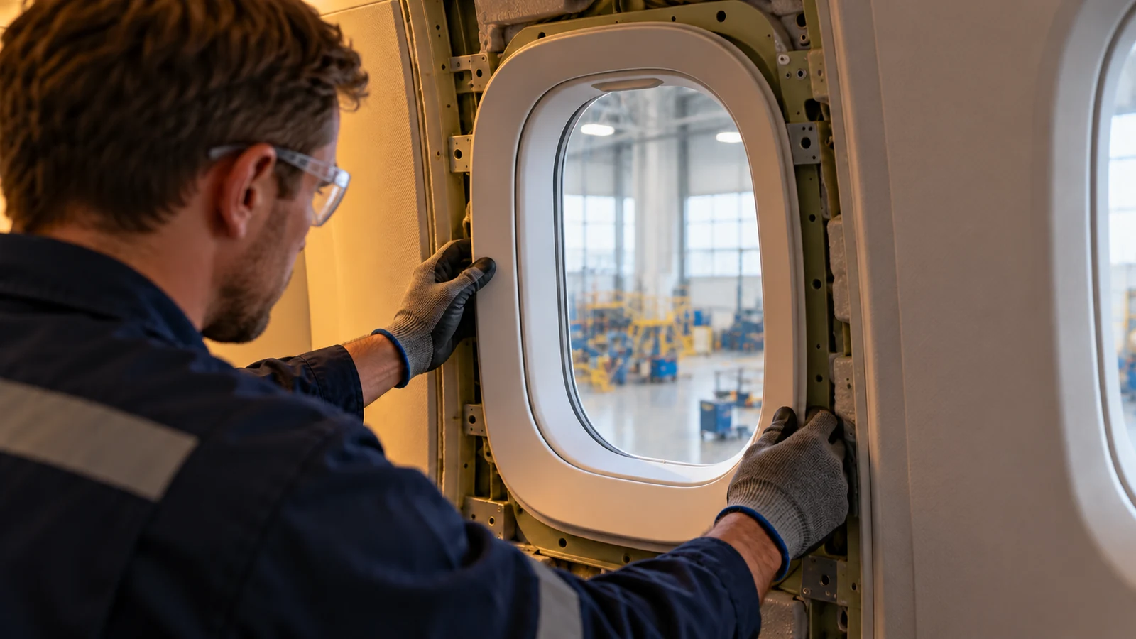
An aircraft window frame is the structural interface around a window opening, not the transparent pane itself. It connects the opening to surrounding fuselage or cabin structure and must match the window assembly, adjacent skin, and installation method. A manufacturing article about the frame should therefore focus on its flanges, curvature, edge geometry, attachment holes, and material route rather than drifting into a general guide to aircraft glazing.
The exact frame design varies by aircraft and program. This guide is not a repair instruction or a substitute for approved structural data. It explains how to review a prototype or custom frame for manufacturability and fit, while leaving material allowables, pressure requirements, and acceptance criteria to the controlled design.
Separate the frame from the window assembly
A window assembly can include the transparent pane, seals, retainers, inner trim, and the structural frame. These elements have different materials and acceptance requirements. The frame’s mechanical drawing should identify which surfaces contact the pane or seal, which flanges attach to the surrounding structure, and which edges remain visible after installation.
Define the installation stack. Show the window opening, surrounding skin or panel, frame flange, fastener locations, seal line, and any trim interface. If the pane is supplied by a different vendor, provide the interface dimensions and the revision that controls them. A small change in pane thickness, seal compression, or flange curvature can affect fit even when the frame’s outer dimensions remain unchanged.
Separate aircraft window frames from generic material-use examples. Existing material content may mention windows as an application, but a dedicated frame article should explain structural shape, manufacture, and installation interfaces. The aviation and aerospace parts page provides the broader industry context without replacing the controlled aircraft definition.
Define curvature, flange, and edge conditions
Frames may follow a curved fuselage surface or use a profile with inner and outer flanges. The drawing should identify the datum scheme that controls curvature, opening size, and mounting position. A simple flatness callout may not describe a curved frame’s function. Use sections and interface coordinates to show how the frame nests against the surrounding structure.
Flange width, thickness transitions, corner radii, and fastener access affect both forming and machining. Tight corners can be difficult to form without wrinkling or to machine without small tools. Thin flanges can deform during clamping or fastening. Edge breaks should be controlled where the frame contacts a seal, pane, or trim; a general edge deburr note may remove material that the interface depends on.

If the design uses composite material, ply orientation, molding route, cure process, trimming, and edge protection may govern the final geometry. If it uses metal, forming or machining may be considered depending on cross-section and quantity. Do not blend these routes into one generic process recommendation; select them against the released design and approved material system.
Select a route that matches the frame architecture
A formed sheet-metal frame can suit a profile with flanges and modest wall thickness, but bend radii, springback, grain direction where specified, and hole position after forming need review. A machined frame may provide controlled local interfaces or a complex profile, but can remove substantial material and require careful support. A composite molded frame may reduce part count or create complex curvature, while bringing tooling, trimming, and inspection considerations.
For early prototypes, the selected process should answer the current question. A machined plastic or aluminum mockup may check packaging and fastener reach, but it may not represent production stiffness, thermal behavior, or the approved structural material. A formed-metal prototype can validate bend and assembly questions only when its material and process are representative enough for that purpose.
Material choice depends on the design authority’s requirements for structure, environment, joining, finish, and traceability. The aerospace materials overview can orient an initial comparison; exact alloy, condition, and product form must come from the controlled specification.
Control attachment and sealing interfaces
The frame must meet the surrounding structure without forcing the pane or seal into an unintended shape. Define the fastener pattern, hole type, edge distance, countersink or bearing surface, and installation sequence. If the frame is bonded or riveted, show the joint details and how sealant, adhesive, or primer is controlled at the interface. These are not interchangeable assembly choices.
Seal contact deserves explicit drawing treatment. State the seal path, contact width, surface condition, and any corners that require a continuous transition. If the seal supplier controls a separate part, use the interface drawing to coordinate compression and fit rather than expecting the frame supplier to infer it.
Finishing may affect the opening and flange dimensions. Identify masked areas, coating boundaries, and whether dimensions are measured before or after treatment. The site’s aerospace surface-treatment guide can support discussion of process planning, but program-specific finish requirements must govern the actual component.
Use prototypes to check installation questions
A frame prototype can answer practical questions: can the part be positioned through the opening, can fasteners be reached, does the flange follow the mating contour, can the seal be installed without wrinkling, and can trim cover the intended edges? These are valuable early checks because they expose problems before a production route is committed.
Make the prototype’s limits explicit. A nonrepresentative material or simplified finish can confirm envelope and access but cannot prove structural strength, pressure integrity, window retention, bird-strike behavior, or airworthiness. Record the drawing revision, material, process, and purpose so that later teams do not confuse a fit model with an approved part.
For a quote, include the assembly model, pane and seal interfaces, curvature data, controlled material, finish, quantity, and inspection expectations. The aerospace sheet-metal fabrication page is relevant if the selected route uses formed sheet construction.
Inspect the frame in its assembly context
Inspection should relate the opening, contact surfaces, flange profile, and mounting holes to the same datum scheme used in assembly. A check fixture or representative mating panel can help assess the contour, while coordinate measurement can document hole positions and local geometry. The measurement method should reflect the frame’s size and whether it is inspected free-state or supported.
Check edges and surfaces that touch a seal or pane for burrs, scratches, and finish buildup. A frame can meet its envelope and still create an installation problem if the sealing land is damaged or a coating changes a critical clearance. Define any required post-finish inspection and ensure the drawing identifies which features are protected.
Part inspection does not establish the complete window assembly’s qualification. The responsible program must define installation, sealing, structural, and system-level acceptance evidence. The aerospace quality and inspection guide can help organize component records and first-article checks.
Frequently asked questions
Is an aircraft window frame the same as the window?
No. The frame is the mechanical or structural interface around the opening; the window assembly may also include panes, seals, retainers, and trim. Their drawings and suppliers may be separate.
Can a prototype frame prove the window is airworthy?
No. A prototype can verify defined fit and access questions. Airworthiness and structural acceptance require the approved design and verification process.
Should the frame be machined or formed?
That depends on the cross-section, curvature, material, quantity, tolerances, and interface requirements. Compare routes against the controlled drawing rather than choosing by part name.
Why specify the inspection support condition?
A curved or thin frame can change shape under fixture force. The support state must match the requirement so measurements reflect the intended assembly condition.

