


An inlet guide vane is a stationary aerodynamic component positioned in an engine flow path. It can turn or condition incoming air before the next stage, so its airfoil profile, edge condition, mounting orientation, and relationship to neighboring vanes matter. The manufacturing challenge is to preserve a controlled aerodynamic shape while also producing a root, platform, or attachment interface that fits the assembly.
Aircraft engine inlet guide vane machining should follow the engine program’s released geometry and material specification. The component’s function and acceptance limits are defined by the engine design authority. This guide focuses on manufacturing readiness: how to protect the airfoil profile, avoid confusing visual finish with aerodynamic conformance, and plan inspection around the actual design.
Contents
- Start from the controlled airfoil definition
- Treat leading and trailing edges as functional features
- Connect the airfoil to its mounting interface
- Select a process around the profile and material
- Control surface condition without over-finishing
- Measure the airfoil with a defined method
- Keep part acceptance tied to the engine baseline
Start from the controlled airfoil definition
Use the released 3D model, drawing, and revision as the source for the airfoil. Confirm the chord, span, section stations, twist, camber, and orientation only to the extent specified by the design package. A generic vane silhouette is not enough to define a functional aerodynamic surface.
Identify the datums that locate the vane in the engine assembly. The root, platform, or mounting feature may establish radial and circumferential position, while another surface controls axial placement. Ensure the manufacturing and inspection references match the engine’s assembly datum scheme.
If the airfoil is defined by profile tolerances or coordinate data, confirm how those data are interpreted and measured. Avoid converting a surface model into a collection of convenient dimensions that no longer control the same shape. The engineering authority should resolve ambiguity before manufacturing begins.
Treat leading and trailing edges as functional features
Leading and trailing edges can influence flow behavior and may be sensitive to radius, thickness, burrs, and local waviness. The design should specify their shape and allowable condition. Do not sharpen, blend, or polish an edge based on visual preference when the drawing defines a specific profile.
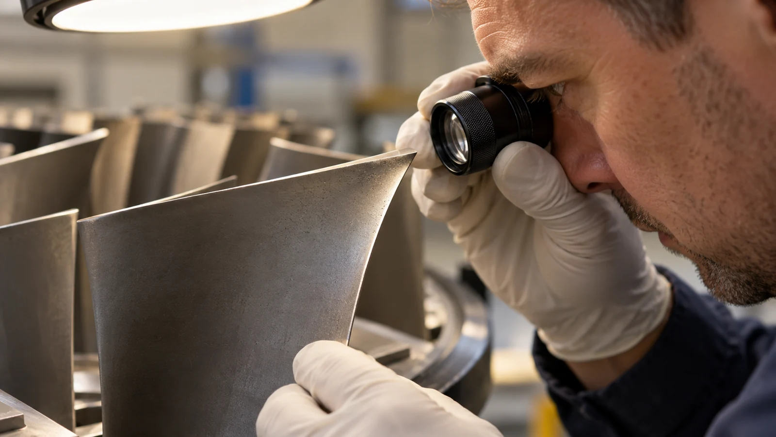
Machining strategy should protect thin edge regions from deflection and damage. Workholding may need to support the vane close to the profile while leaving tool access. Consider the sequence for roughing, finishing, and deburring so the final edge does not become a hand-finished approximation.
Inspection should focus on the edge characteristics that the design authority identifies. A visual check can reveal damage but cannot establish a controlled radius or airfoil profile. If edge measurement is difficult, agree on a suitable method and its limitations before release.
Connect the airfoil to its mounting interface
The root or platform transfers load into the engine structure and locates the airfoil relative to the flow path. Its position, contact faces, retention features, and orientation must be coordinated with the mating case or carrier. A correct airfoil profile in the wrong circumferential orientation does not satisfy the assembly definition.
Review how the vane is retained and whether the interface permits thermal movement. The engine design authority determines whether the part is fixed, floating, bonded, brazed, or retained through another approved method. Joining or coating can change geometry and material properties, so the sequence must be controlled.
Check the tolerance stack from the root datum through the vane surface to the engine assembly. If multiple vanes form a circumferential set, the design should define indexing and any required matching or pairing. Manufacturing records should identify the actual part revision and any lot or position assignment when specified.
Select a process around the profile and material
Process choice depends on vane size, profile complexity, material, quantity, and engine-program requirements. CNC machining may suit an integral or low-volume component when the geometry is accessible and the material condition is appropriate. Casting, forging, additive processes, or other routes may be selected for different designs, but each requires its own process controls and acceptance plan.
For machining, consider tool reach, cutter contact, thin-wall stability, and how the root is held without distorting the airfoil. Multi-axis operations can reduce setup changes, yet toolpath strategy and inspection still need to be validated against the controlled profile. A process description alone does not guarantee aerodynamic conformance.
Jucheng’s CNC machining capability can be reviewed for the released geometry, material, and inspection requirements. Any prototype or process trial must be clearly identified and must not be treated as an engine-qualified part unless the program’s approval path says so.
Control surface condition without over-finishing
Surface texture, tool marks, coatings, and local blending can affect the final profile or the engine’s surface requirements. The specification should define the required surface condition and any prohibited defects. Avoid adding an arbitrary roughness value without a source, measurement direction, and defined evaluation area.
Finishing operations can remove material unevenly, especially at thin edges and root transitions. If hand blending is permitted, define its limits and inspection method. If a coating or protective treatment is required, clarify masking, thickness allowance, and post-treatment acceptance.
Cleanliness and handling controls may be important for engine components. Protect the airfoil from nicks and contamination between operations, and ensure packaging does not damage the edges. The program’s material, process, and cleanliness specifications control the details.
Measure the airfoil with a defined method
Profile inspection may use a CMM, optical scanning, dedicated fixture, or another method selected for the part and tolerance. The method should compare the measured surface with the controlled definition using a documented alignment strategy. A color map is useful only when its datum alignment and acceptance limits are specified.
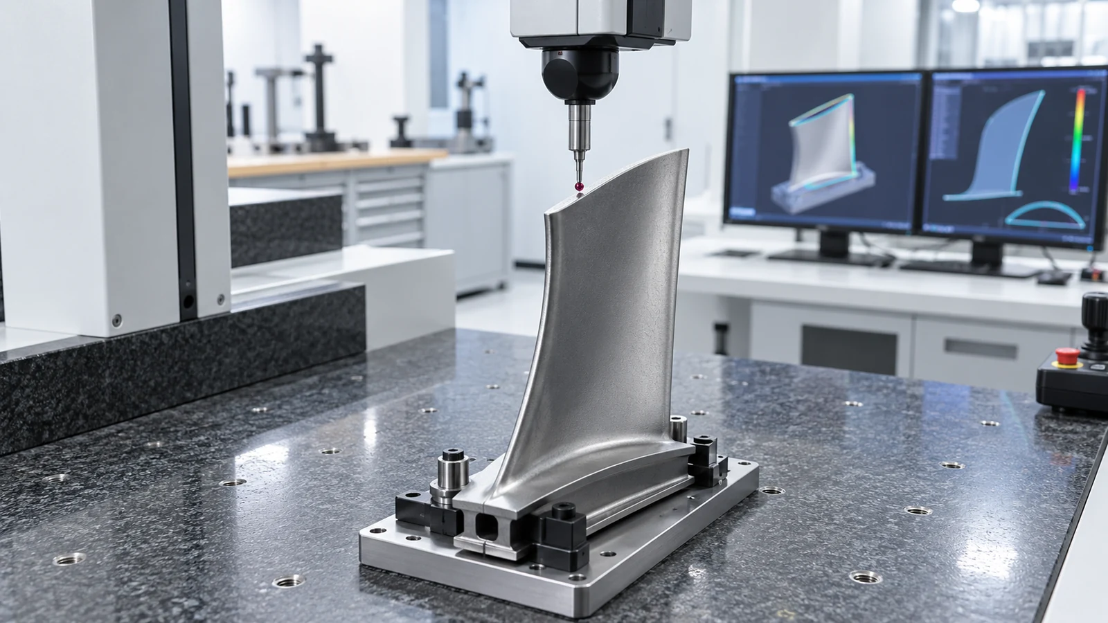
Check the root and mounting features separately from the aerodynamic surface, then evaluate their relationship. If multiple stations or sections are measured, identify where they are taken and how the results are reported. Measurement uncertainty should be suitable for the tolerance being accepted.
First-article records should include the model and drawing revision, material traceability, process state, equipment, alignment method, and actual results for critical characteristics. If finishing occurs after initial measurement, recheck affected features in the final condition.
Keep part acceptance tied to the engine baseline
Dimensional inspection establishes conformance to listed characteristics. It does not by itself prove engine efficiency, durability, or operational performance. Those outcomes are assessed under the engine program’s analysis and test plans. Keep the claim and the evidence aligned.
A useful procurement package includes the controlled geometry, material and condition, finish and edge requirements, datum scheme, inspection method, quantity, traceability, packaging, and approved deviation process. If the vane is one member of a matched set, define identification and pairing rules.
When an engineering change alters twist, profile, edge thickness, root interface, or finish, update the manufacturing baseline and review the affected analysis. A visually similar vane may not be interchangeable with the released design.
The airfoil and its root form one controlled part
Reliable aircraft engine inlet guide vane machining preserves the specified airfoil while maintaining a measurable connection to the engine mounting interface. A disciplined process protects thin edges, controls the root datum, manages the final surface condition, and reports inspection in a way that the engine team can evaluate. That is more useful than describing a vane as merely “precision machined.”

