


Robotics Design Guidelines: DFM Best Practices for High-Precision Mechanisms
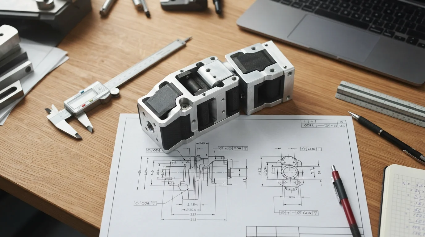
How do you design robotic components for manufacturing? The core principles of Design for Manufacturability (DFM) in robotics require: providing adequate 5-axis cutter clearance for precision bearing journals in CAD, integrating continuous internal hollow-bore channels to protect wiring harnesses from rotational pinch wear, designing integrated radial heat-sink fins directly on high-torque servo motor mounts, and applying topological pocketing (hollowing with reinforcing ribs) to maximize structural rigidity while minimizing joint rotational inertia. Following practical robotics design guidelines ensures that mechatronic assemblies achieve zero-backlash motion and micro-millimeter trajectory repeatability without driving up CNC cycle times.
Balancing structural stiffness against total arm mass dictates how fast an articulated robot can accelerate without suffering from terminal endpoint oscillation. Integrating manufacturing realities during the 3D modeling phase eliminates costly tooling collisions, reduces assembly friction, and speeds up production readiness across industrial, collaborative, and humanoid robotics programs.
Designing for Precision Motion: Minimizing Backlash and Elastic Deflection
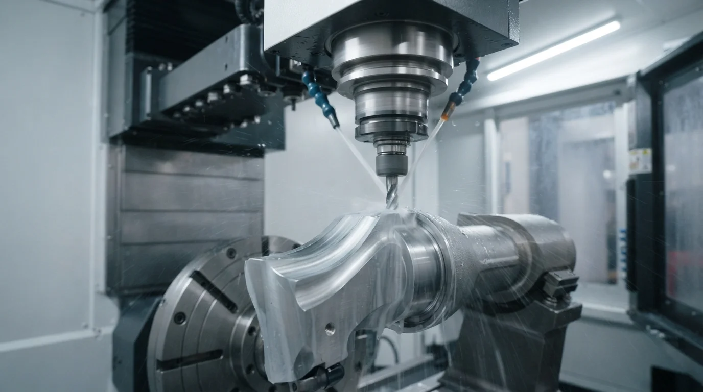
A robotic arm functions as a series of cantilever beams linked by rotational pivots. Any micro-deflection at the base joint multiplies exponentially down the kinematic chain, causing significant positional error at the end-effector. Utilizing high-strength AL7075-T6 aluminum allows mechanical engineers to design thin-walled structural link pockets (1.2 mm to 1.5 mm web thicknesses) that deliver superior torsional rigidity without adding parasitic weight.
Key design rules to eliminate mechanical play and maximize structural rigidity include:
- Dual-bearing support spans: Space rotational bearings as far apart as packaging envelopes permit to maximize moment load resistance and prevent axial tilting.
- Symmetrical rib architectures: Place diagonal cross-ribs inside hollow link sections to resist multi-axis torsional twisting during high-speed emergency stops.
- Direct harmonic drive mounting: Design mounting bolt patterns directly on the main link frame to eliminate intermediate adapter plates and reduce tolerance stacking.
Integrating Internal Cable Routing and Sensor Mounts in 3D CAD
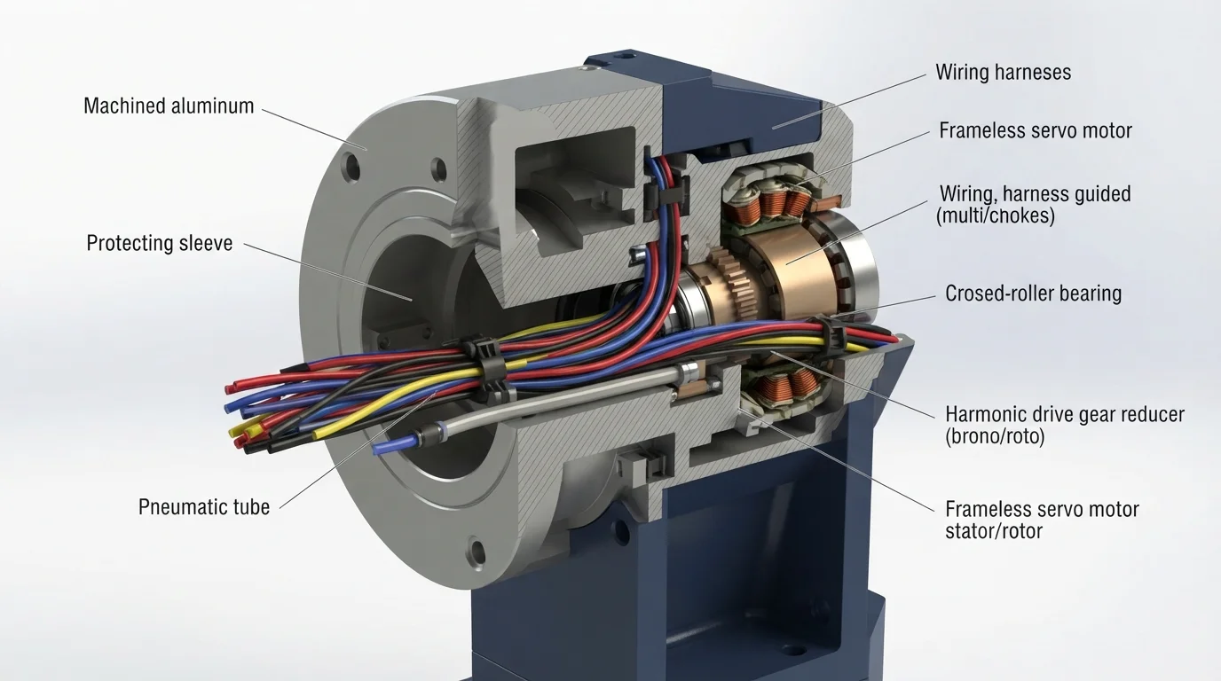
External cable harnesses snag on fixtures, wear out from continuous flex fatigue, and restrict arm range of motion. Modern mechatronic packaging routes high-density DC busbars, encoder lines, and pneumatic tubes straight through hollow-bore actuator centers. When product designers establish their robotics design guidelines, leaving generous bending radii (at least 8x to 10x cable diameter) and chamfering internal conduit edges prevents wire chafing during continuous 360-degree rotation. Discussions across robotics hardware communities on Reddit and Facebook emphasize that failing to chamfer internal aluminum conduit entries is the primary cause of early field harness failure.
Evaluating geometric parameters across critical robotic features outlines essential CAD modeling targets:
| Caractéristique de conception | Recommended CAD Value | Avantage mécanique principal |
|---|---|---|
| Internal Cable Conduits | R3.0 mm minimum edge chamfer, bend radius ≥ 10x cable OD | Prevents harness insulation chafing and extends flex cycle life |
| Motor Cooling Fins | 1.5 mm root thickness, 3:1 depth-to-spacing ratio | Maximizes convective heat dissipation without adding excessive weight |
| Bearing Journal Fillets | R0.2 mm to R0.4 mm undercut relief groove | Allows bearings to seat flush against shoulder faces without corner radius interference |
Thermal Dissipation Design for High-Torque Servo Motor Mounts
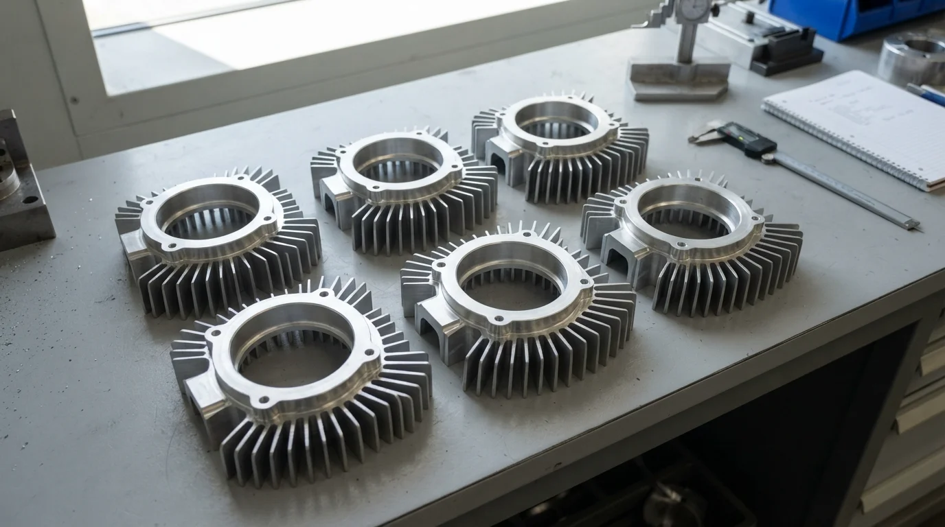
Frameless brushless DC motors generate intense localized resistive heat when holding continuous stall torque. If this heat cannot escape, stator temperatures climb rapidly, degrading neodymium magnet strength and increasing thermal expansion that binds tight bearing clearances. Integrating conductive radial cooling fins directly into CNC-machined 6061-T6 or 7075 aluminum motor housings provides a direct thermal conduction path to ambient air, keeping motor operating temperatures well within safe limits.
5-Axis Tool Access, Corner Radii, and Deep Pocket Machinability
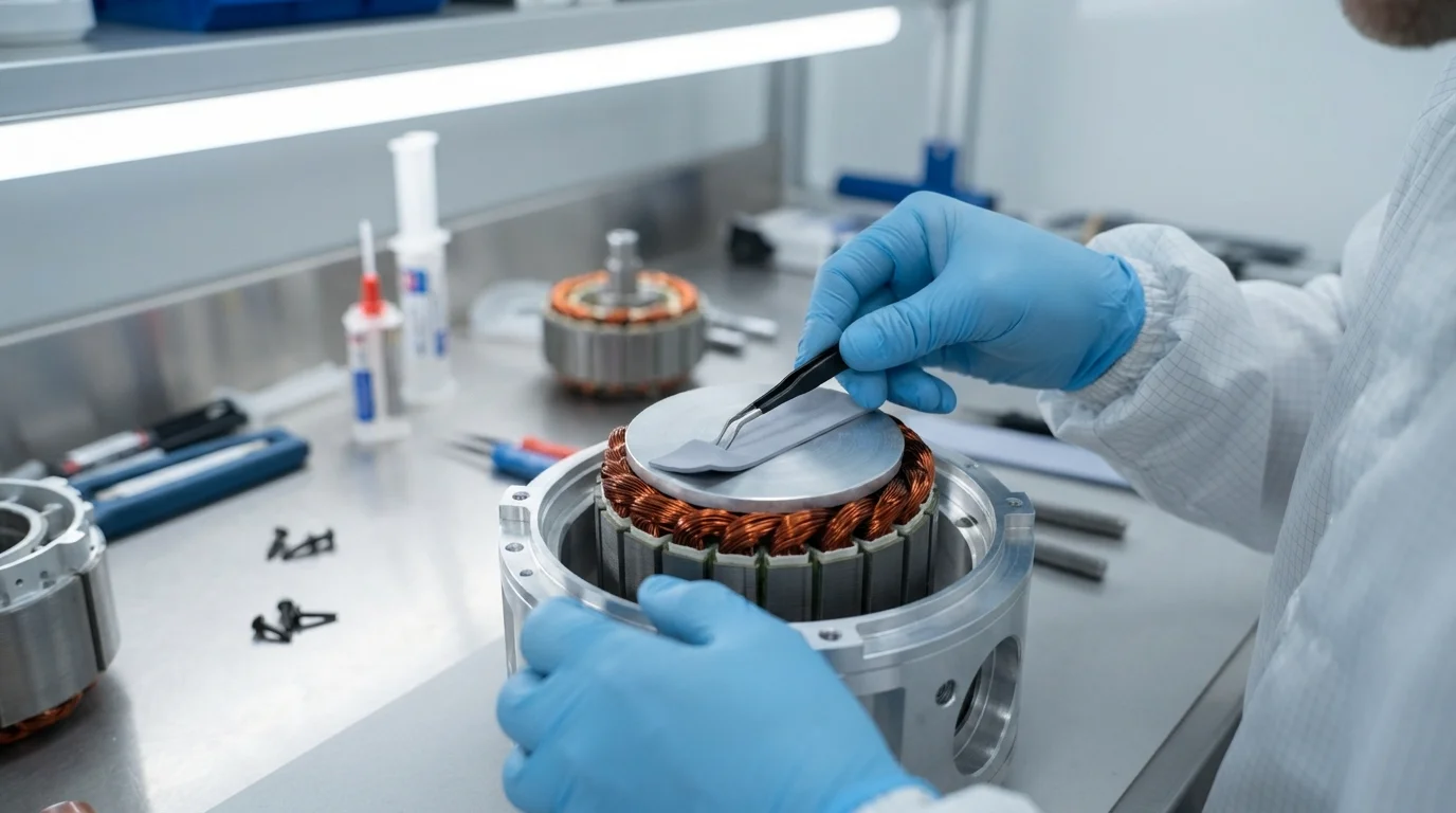
Complex asymmetric arm linkages often require cutting deep internal cavities where cutting tools must reach without vibrating or hitting adjacent sidewalls. Designing CAD geometry with usinage CNC 5 axes in mind reduces cycle times and tooling wear:
- Standardize internal pocket radii: Specify corner radii to at least 1/3 of total pocket depth (e.g., R5 mm fillet for a 15 mm deep pocket) so rigid endmills can cut at full feed rates.
- Maintain line-of-sight spindle clearance: Leave at least 15 degrees of draft or clear conical space around deep bearing bores to prevent multi-axis spindle collisions.
- Avoid micro-threaded blind holes: Design internal tapped holes with adequate tap drill relief (at least 2x pitch deeper than usable thread) to avoid breaking taps inside expensive arm castings.
Assembly Fitment Guidelines and Kinematic Precision Maintenance
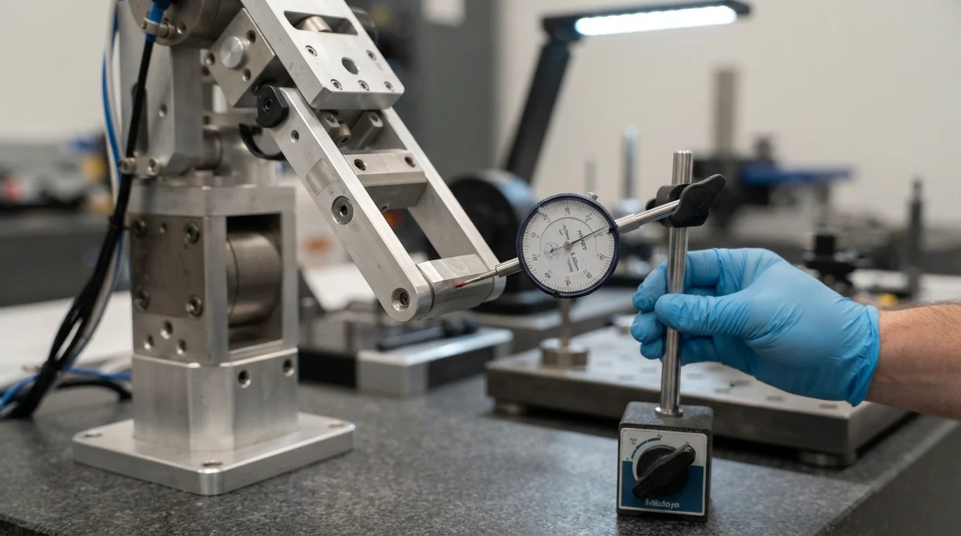
Flawless CAD design means nothing if parts cannot be assembled without mechanical binding. Incorporating dual precision locating dowels, standardized fastener spacing, and accessible wrench clearance into your models ensures rapid, repeatable assembly on the factory floor.
Key assembly and maintenance design rules include:
- Diamond and round pin pairings: Use one round dowel pin to locate X-Y position and one diamond pin to lock rotation, preventing over-constraint during link assembly.
- Accessible wrench tool clearance: Maintain at least 1.5x socket diameter clearance around all structural cap screws to allow calibrated digital torque wrenches to engage squarely.
- Wear-resistant polymer bushings: Seat self-lubricating Delrin (POM) or PEEK sleeves inside dynamic pivot joints to isolate aluminum frames from direct rotational friction.
Foire aux questions (FAQ)
1. What is the biggest design mistake in robotic arm development?
The most common mistake is neglecting concentricity tolerances between bearing bores across joint halves and failing to leave adequate tool clearance, causing gear binding, severe backlash, or impossible manual assembly.
2. How do engineers prevent wire harness fatigue in rotating robot joints?
Engineers route high-flex cables through hollow-bore actuators along the neutral rotational axis, ensuring conduit edges feature generous R3+ mm chamfers and generous bend radii.
3. What is the minimum recommended wall thickness for machined robotic aluminum links?
A minimum structural wall thickness of 1.2 mm to 1.5 mm is recommended for 7075-T6 aluminum pockets; walls thinner than 1.0 mm tend to chatter under high-speed milling and deflect under heavy joint loads.
4. Why should motor mounting brackets feature integrated cooling fins?
High-torque frameless servo motors generate intense heat during continuous stall holding; integrated aluminum cooling fins provide a direct conductive and convective heat-sink to prevent thermal demagnetization.
5. How does DFM software simulation prevent multi-axis machining collisions?
CAM kinematic simulation animates machine spindle heads, tool holders, and rotating tables against 3D CAD models to detect interference zones before real metal cutting begins.
6. How does Jucheng Precision assist robotics engineers with DFM optimization?
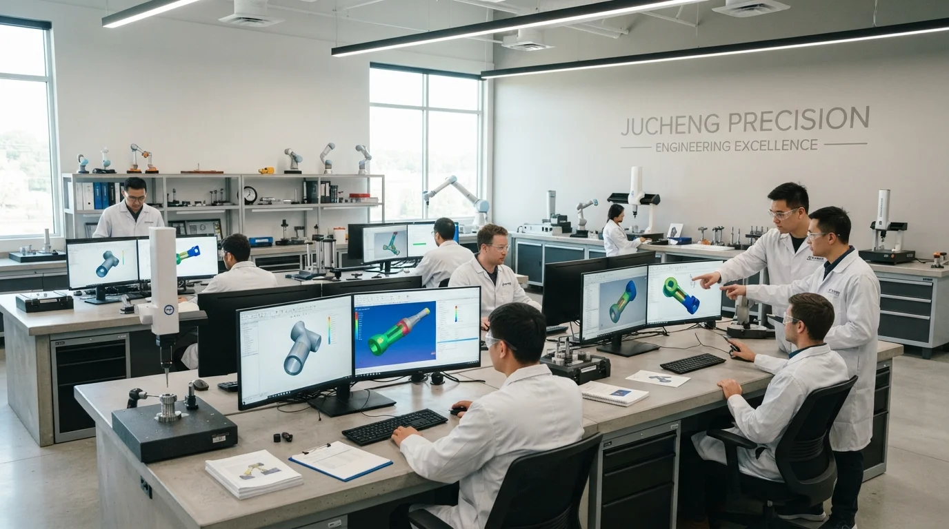
Jucheng Precision delivers automated 24-hour free DFM reviews, kinematic toolpath collision checks, wall-thickness audits, and bearing fit tolerance recommendations under ISO 9001 systems.
Why Choose JUCHENG for Your Robotics Sourcing
Achieving zero-backlash kinetic motion and seamless assembly requires an experienced manufacturing partner with deep DFM expertise and multi-axis CNC infrastructure. JUCHENG supports robotics innovators by delivering comprehensive analyses DFM gratuites 24h/24 reviews that analyze bearing fit tolerances, cable clearance channels, and structural pocketing ratios prior to cutting metal stock. Founded in Shenzhen in 2012 with an 8,000-square-meter facility in Dongguan, our factory houses 150+ advanced machines, including 25+ high-performance 5-axis Haas and Mazak milling centers alongside dedicated sheet metal and rapid tooling cleanrooms [9.10].
Backed by ISO 9001, ISO 14001, ISO 13485, and IATF 16949 certifications, our engineering teams ensure that implementing practical robotics design guidelines achieves sub-micron bearing concentricity, zero backlash alignment, full material traceability, and absolute batch consistency.
Ready to Optimize Your Robotics CAD Design for Production?
Upload your 3D models today to receive instant feedback, competitive pricing, and professional DFM analysis from our seasoned engineering experts. Let JUCHENG bring your complex designs to life with unmatched speed and reliability!

