


A satellite avionics enclosure is a mechanical package for electronics, connectors, cables, thermal interfaces, and mounting hardware. The enclosure must do more than surround a circuit board: its opening pattern, internal supports, bond surfaces, cover joint, and access features determine whether the equipment can be assembled and maintained as intended. A useful manufacturing review therefore begins with the electrical and thermal interfaces, then works outward to the housing geometry.
The term covers many architectures, from a machined housing to a formed sheet-metal case or a hybrid assembly. This guide focuses on how to define and manufacture the mechanical enclosure without assuming a particular spacecraft program, shielding level, or qualification basis.
- Start from the electronics interface map
- Turn packaging into manufacturable geometry
- Define grounding and shielding intentionally
- Coordinate heat paths with enclosure structure
- Choose between machined, formed, and hybrid construction
- Verify fit, finish, and interface evidence
- Frequently asked questions
Start from the electronics interface map
Before designing walls or pockets, collect the board outline, connector locations, cable exit directions, mounting points, service clearances, and thermal interface requirements. Mark which features are controlled by the electronics design and which belong to the enclosure. If a connector is moved late in the layout, it may collide with a wall, compromise a panel cutout, or reduce tool access for machining.
Build a simple interface map that shows board support points, standoffs, connector panels, cover fasteners, grounding features, and any heat spreader or cold plate. Identify the datum from which the board and connectors are located. This prevents a common mismatch: the enclosure’s holes are referenced from one edge while the circuit-board assembly is positioned from another, leaving an accumulated tolerance stack at the connector face.
Also define the intended service strategy. Does the board slide into rails, mount from the base, or attach to a removable tray? Is the cover removed in the field, or is the enclosure opened only during integration? That answer affects fastener selection, thread engagement, access windows, and the need to protect components during assembly.
Turn packaging into manufacturable geometry
Machined housings can integrate walls, ribs, standoffs, and mounting features, reducing part count. However, deep cavities, thin walls, and internal corners can increase tool reach and inspection difficulty. A formed enclosure may reduce material removal and suit a multi-piece design, but bends and joints introduce their own stack-up, edge, and assembly controls. Neither approach is automatically superior.
Model the interior with realistic tool and assembly access. A design may fit the CAD envelope yet leave no path for a driver, board insertion, connector mating, or inspection probe. Keep wall thicknesses as consistent as practical, use radii a tool can produce, and avoid fragile tabs that can deform during handling. If the cover joint is a sealing or EMI interface, define how the contact surface is produced and maintained around corners and fastener interruptions.
For a CNC-machined body, define where the stock is held and which surfaces remain available as datums during each setup. For formed sheet construction, show bend lines, relief geometry, grain or material-direction requirements when applicable, and how the finished panel relates to the mating assembly. The aerospace sheet-metal fabrication guide is relevant when enclosure panels are made from formed sheet rather than a single billet.
Define grounding and shielding intentionally
Do not rely on a generic “conductive enclosure” note to define electrical behavior. The electrical design should specify where bonding occurs, which surfaces must remain conductive, how coatings are masked, and how the cover or removable panel maintains contact. The mechanical drawing can then show contact lands, fastener spacing, surface treatment zones, and any conductive gasket interface.
Shielding and grounding are system requirements, not properties that can be inferred from metal appearance. A painted, anodized, plated, or conversion-coated surface may behave differently at an electrical contact, and a small interruption in a seam can matter depending on the frequency range and system design. The enclosure manufacturer can fabricate the controlled geometry; electrical verification and acceptance criteria must come from the program’s engineering documents.
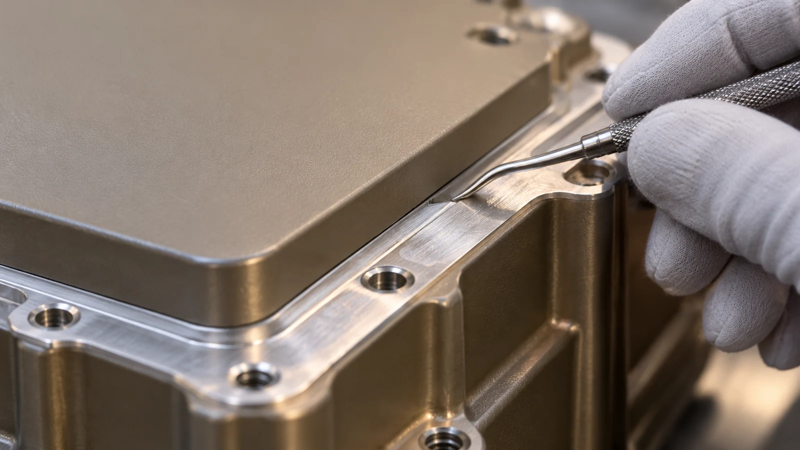
Separate environmental sealing from electrical bonding in the requirements. If a gasket is used, specify its material, compression range, joint geometry, and replacement method. If the design uses bare-metal contact, define corrosion controls and how the interface remains serviceable. These distinctions help avoid a finish that satisfies one requirement while undermining another.
Coordinate heat paths with enclosure structure
Electronics heat can leave through a baseplate, a conductive interface, a chassis rail, or a dedicated thermal control component. The enclosure drawing should identify the intended path and its mating surface. If the board conducts heat through a pad or spreader, the relevant mounting plane, flatness, and contact location need a clear datum. A tall standoff or uneven contact can create assembly stress or inconsistent thermal coupling.
Material selection affects mass, stiffness, machinability, corrosion behavior, and thermal conductivity. Aluminum is common in mechanical packaging discussions, but the final alloy and condition should follow the approved design. Material choice alone does not prove thermal adequacy; the system’s contact resistance, interface material, board layout, and heat rejection path also matter.
The site’s aerospace materials overview can help compare candidate stock families. If the system uses a liquid-cooled component, keep its ports and pressure boundaries within the separate cold-plate definition instead of treating the enclosure as the cooling device by default.
Choose between machined, formed, and hybrid construction
A machined enclosure can be attractive for prototypes, complex internal geometry, or low-volume parts that benefit from integrated features. Its cost and risk often depend on material removal, tool access, fixture strategy, and the number of operations required to reach internal faces. A formed housing can use less stock and support larger panels, but it may require separate covers, rails, inserts, joining operations, or finishing steps.
A hybrid design can reserve machining for precision interfaces while using formed panels for less demanding covers. This can help when connector patterns and thermal surfaces need controlled geometry but the outer shell is broad and thin. The tradeoff is added joints and tolerance accumulation. Use a sectioned assembly model to identify where alignment is established and where a seam is acceptable.

Process selection should consider quantity and revision maturity. Early prototypes may benefit from a route that permits fast changes to cutouts and mounting points. A later build may favor a more repeatable architecture after the interfaces are stable. The aerospace manufacturing process guide provides a general comparison framework; the drawing and program controls govern the actual route.
Verify fit, finish, and interface evidence
Inspection should cover the enclosure’s controlled mechanical interfaces: board datums, connector apertures, mounting holes, cover contact surfaces, thermal base, and finish boundaries. The report should identify the drawing revision and measurement method. If assembly fit is important, a fixture or representative mating part may reveal issues that isolated dimensions cannot.
For a prototype, define whether the goal is to confirm board fit, connector reach, cover closure, cable routing, thermal contact, or shielding performance. Do not use a mechanical fit check as evidence of EMI performance, thermal qualification, or flight approval. Those require separate tests and acceptance criteria.
Before release, verify that the enclosure, board, gasket, fasteners, and coating share the same revision and interface assumptions. A small mismatch in board thickness or connector stack can move the faceplate even when each component individually meets its own drawing. The aerospace quality and inspection page can help structure first-article evidence and change control.
For the wider hardware-development context, the aviation and aerospace prototyping page connects enclosure planning to the broader project scope; it does not replace component-specific acceptance criteria.
Frequently asked questions
Should a satellite avionics enclosure be machined from one block?
Not by default. A monolithic housing may integrate features, while formed or hybrid construction may reduce material removal or suit larger covers. Compare interfaces, access, quantity, mass, and revision stability.
Does an aluminum enclosure automatically provide EMI shielding?
No. Shielding depends on the complete electrical design, seam continuity, contact surfaces, apertures, grounding, and test criteria. Material alone is not proof of system performance.
Which dimensions matter most for assembly?
Prioritize board datums, connector apertures, mounting patterns, cover interfaces, and thermal contact surfaces. The drawing should show how these features relate to one another.
Can the enclosure supplier choose a coating?
The supplier can advise on manufacturability, but the approved design must define coating type, protected zones, conductivity needs, and dimensional effects.

