


A bone plate is not defined by its outline alone. Its contour, hole pattern, countersinks, local thickness, edges, and surface condition work together as a part designed to mate with a particular system. In manufacturing, that means bone plate machining has to preserve a chain of relationships from the drawing to the finished part. A hole can measure correctly and still sit in the wrong place relative to a bend, slot, or datum.
This article addresses the supplier-side engineering questions behind machined bone plates: what should be controlled on the drawing, how to plan a prototype or repeat build, and how to make inspection evidence useful. It does not make clinical recommendations or define the requirements for any specific implant. The device owner and approved design documentation remain the authority for the finished product.
- Read the hole pattern as a set of interfaces
- Translate the model into a machining datum plan
- Control material identity and condition
- Treat edges and surface condition as designed features
- Make inspection match the drawing’s intent
- Keep revisions and manufacturing records connected
- A manufacturing release checklist for the supplier handoff
Read the hole pattern as a set of interfaces
Bone plates may contain round or elongated holes, countersinks, locking features, contours, and local transitions. Each feature has a relationship to the plate’s shape and to the mating hardware. A drawing review should identify which dimensions locate the holes, which control their form, and which surfaces are intended to meet another part. A coordinate table without a clear datum scheme can leave the supplier unsure where to establish the part.
Begin with a feature-by-feature review. For each hole or slot, confirm the nominal location, orientation, edge distance, and any specified countersink or thread detail. Then review those features as a pattern relative to the plate contour. This catches a common documentation gap: individual hole coordinates may be present while the reference edge, centerline, or local profile that governs the pattern remains ambiguous.
The model and drawing should agree about the finished state. If a surface is intended to remain as-machined, polished, blasted, or otherwise treated, identify that requirement and how it affects dimensions. Distinguish functional surfaces from appearance-only surfaces so the manufacturing plan can allocate effort to the characteristics the design actually controls.
For development parts, write down what the prototype is being used to learn. Is it checking the fit of a mating component, the access of a tool, or the consistency of a contour? A prototype that answers one question should not be treated as evidence for a different requirement. The intended evaluation helps decide which features need formal inspection and which observations are exploratory.
Translate the model into a machining datum plan
A thin plate can be straightforward to cut and still difficult to hold flat and repeatable. Clamping can bend the part; releasing the fixture can allow it to spring back. If the machining plan references a temporary edge or a rough blank surface, the resulting hole pattern may shift relative to the final contour. The datum scheme should therefore connect the part’s design references with the surfaces used to locate it through the operations.
Where both sides of a plate contain features, plan how the second side will be registered to the first. A fixture, locating pins, reference holes, or another method may support that transfer, but the choice depends on the geometry and the required result. The drawing should make clear which features are the reference; the process plan should state how the setup recreates it.

Material removal can also change the plate’s condition. Large pockets, long slots, or asymmetric contours may leave local sections less stiff than the starting blank. A process plan can sequence roughing and finishing so critical surfaces are completed after the main stock removal, then inspect the part in an agreed free or supported state. Avoid judging the result only while it is pulled against a fixture if the functional requirement applies after release.
If a plate needs a contoured profile, identify where the contour is controlled and how it will be checked. A nominal 3D surface may not be enough for a machinist to know which sections are critical. Sections, profile tolerances, reference points, and inspection notes can make the intended shape more explicit.
Control material identity and condition
Material selection belongs to the device design authority. The manufacturing package should state the exact grade, form, condition, and applicable purchasing or test documentation required for the order. Do not substitute a broad label such as “titanium” or “stainless steel” for a controlled material callout when the drawing or quality plan specifies more detail.
Before machining, connect the received material identity to the job and revision. For a build that requires traceability, record the source documentation and maintain the relationship between the stock and finished parts according to the customer’s quality requirements. Cutting stock into smaller blanks should not sever that identity trail. The specific records are defined by the program, not by a generic article.
Machining strategy should reflect the specified material’s behavior, tool access, feature size, and surface requirements. Titanium and stainless steel are both used in medical manufacturing, but their exact grades and conditions are not interchangeable. This site’s medical titanium precision machining guide et medical device materials overview provide broader context; the component drawing must govern the actual part.
Treat edges and surface condition as designed features
Edges around holes, slots, and plate contours can affect assembly and inspection. Burrs may interfere with a mating component or obscure a feature. A deburring requirement should describe the acceptable edge condition, and the inspection plan should confirm that the process did not damage a thin section or alter a critical edge.
Surface finish is similarly specific. A general finish callout may not describe every surface equally. Identify which surfaces require a defined condition and whether subsequent polishing, passivation, coating, or cleaning is part of the supplied scope. If secondary work follows machining, check any dimensions or edges that can change during that operation afterward.
Handle thin parts so they remain identifiable and protected between operations. Contact marks, scratches, or mixed revisions can complicate both acceptance and traceability. Packaging and handling instructions should follow the buyer’s documented requirements rather than assumptions based on the part’s appearance.
Make inspection match the drawing’s intent
A useful inspection plan maps each critical characteristic to a measurement approach and reference. Hole diameter, position, countersink form, contour, thickness, and flatness may require different methods. Decide which are first-article checks, which are repeated during a run, and what record format the buyer needs.
For a pattern of holes, measuring each diameter without checking the pattern location can miss the key interface. For a contour, a few hand measurements may not establish the full profile requirement. The measurement method should be able to reach the feature and should use the same datum logic as the drawing. If a feature is inaccessible or its tolerance is unclear, resolve that before production rather than allowing the report to become a list of assumptions.
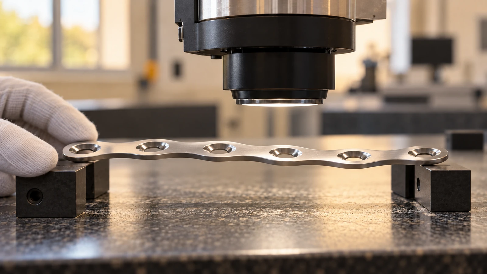
Define the condition of the part during measurement: supported, unclamped, or held in a specified fixture. If the plate relaxes after release, that condition can change the result. The drawing owner and supplier should agree how it will be evaluated. The final report should identify the drawing revision and actual part state inspected.
Keep inspection evidence tied to the question being asked. A dimensional report may show that a part matches selected drawing characteristics, but it does not by itself establish clinical performance or approval for use. That boundary should remain clear in supplier communications and records.
Keep revisions and manufacturing records connected
Bone plate designs can change hole positions, contours, slots, or surface requirements. A revision change should identify what moved and whether the prior fixture, toolpath, and inspection program remain valid. Avoid relying on a filename alone to identify the controlling model. The purchase order, drawing, model, and inspection report should refer to the same release.
When the geometry changes, assess both the direct feature and its relationships. Moving one hole may affect spacing to adjacent holes, edge distance, assembly access, or a pattern datum. Record whether a change is limited to a prototype or has become part of the controlled design. This helps the supplier avoid mixing parts from different revisions.
For repeat builds, make the manufacturing record explain the setup, material identity, critical operations, and inspection references at a level agreed with the customer. The aim is a clear handoff, not paperwork for its own sake. A drawing that communicates design intent reduces interpretation; a process record that captures the approved route helps repeat the agreed result.
A manufacturing release checklist for the supplier handoff
Before sending a bone plate package for quote or manufacture, review the file set in the order a supplier will use it:
- Released geometry: confirm that the model, drawing, and revision agree, including the hole pattern, contour, countersinks, and any section views.
- Material and condition: state the approved grade, form, condition, and required source documentation. Do not leave a family name to stand in for the controlled specification.
- Manufacturing scope: mark which surfaces are machined, which receive secondary finishing, and what edge condition is expected.
- Inspection references: define the datums, measurement condition, critical characteristics, and report needed for the build.
- Program boundary: explain whether the part is exploratory, a first article, or a repeat build, and avoid treating one purpose as evidence for another.
If one item is unknown, label it as an open decision and route it to the design owner. That is more useful than allowing an assumption to become an undocumented part feature. Good bone plate machining starts with a drawing that explains the hole pattern, contour, datum scheme, material, and finished condition. A supplier can then plan support, machining, finishing, and inspection around the defined interfaces.

