


Concevoir des boîtiers électroniques de précision n'est plus une question de calculs manuels par essais et erreurs sur le sol de l'atelier. Passer à des plateformes avancées de conception de tôlerie 3D permet aux équipes d'ingénierie de valider les dégagements structurels dans un environnement virtuel tout en automatisant les calculs de mise à plat pour correspondre à l'outillage de pliage réel. Cette approche de modélisation numérique d'abord est la clé pour prévenir des erreurs d'assemblage coûteuses, en garantissant que chaque bride pressée s'aligne parfaitement avec les circuits imprimés internes et les ports de connecteurs.
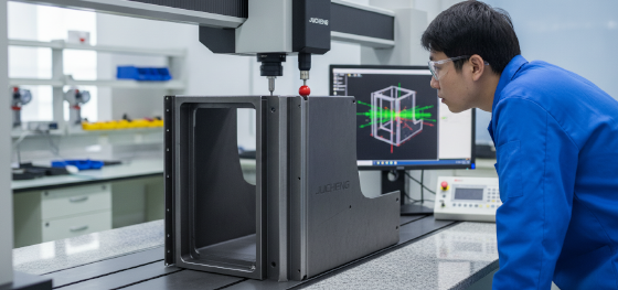
Le dessin bidimensionnel traditionnel repose fortement sur l'interprétation géométrique humaine, laissant votre projet vulnérable à des déductions de pliage inadaptées et à des collisions structurelles négligées. Lorsque les pièces sont envoyées en production avec des dimensions à plat incorrectes, elles se déforment ou s'étirent hors tolérance sous la presse. L'utilisation de la validation de modèle tridimensionnel élimine complètement ces risques physiques, fournissant des schémas à plat prêts à découper directement à la production.
Examinons comment la modélisation virtuelle prévient les interférences physiques, explorons comment les modules CAO calculent l'allongement précis du matériau à l'aide de tables de pliage personnalisées, et passons en revue le flux de données automatisé de la géométrie 3D au code G de la machine.
contenu :
Pourquoi la modélisation 3D est essentielle pour les boîtiers en tôle
Logiciels populaires : SolidWorks et modules de tôlerie
Du modèle 3D au code G machine
Téléchargez vos fichiers STEP/IGES 3D chez JUCHENG pour des devis instantanés
FAQ : Questions critiques sur la conception de tôlerie 3D
Pourquoi la modélisation 3D est essentielle pour les boîtiers en tôle
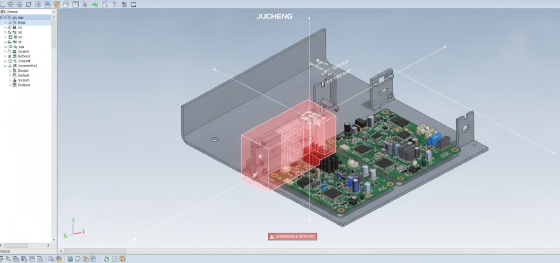
Quels défauts de conception la modélisation 3D virtuelle peut-elle révéler avant le début de la fabrication ?
La modélisation virtuelle identifie les collisions structurelles, les mauvais alignements de brides et les dégagements pour l'insertion de matériel, empêchant ainsi les défaillances d'assemblage physiques.
Un dessin à plat peut facilement masquer une interférence géométrique, mais l'assemblage d'un châssis électronique multi-composants dans un espace virtuel expose chaque collision. En exécutant une analyse d'interférence automatisée dans le logiciel CAO, les concepteurs peuvent vérifier que les circuits imprimés internes, les ventilateurs de refroidissement et les guides de cartes s'adaptent parfaitement à l'intérieur de la coque pliée.
De plus, la modélisation virtuelle vous permet de vérifier les dégagements pour l'installation de fixations à clin auto-poinçonneuses (telles que les écrous PEM et les entretoises). Cela garantit que l'outillage de presse peut physiquement accéder aux trous de montage sans entrer en collision avec les brides pliées adjacentes. Cela fournit un prototype numérique complet qui réduit considérablement votre délai de développement de produit.
Logiciels populaires : SolidWorks et modules de tôlerie
Quels modules CAO sont préférés pour la conception de tôlerie de haute précision ?
SolidWorks, Autodesk Inventor et Creo Parametric disposent de modules de tôlerie dédiés qui calculent l'allongement précis du matériau à l'aide de facteurs K personnalisés et de tables de pliage.
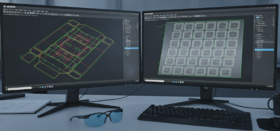
Dans les suites de CAO modernes, les modules de conception de tôlerie 3D s'appuient fortement sur les limites d'étirement élasto-plastiques du matériau. Des programmes comme SolidWorks permettent aux concepteurs de saisir un facteur K précis ou de sélectionner des tables de pliage vérifiées empiriquement. Cette intégration mathématique garantit que lorsque vous concevez une bride, le logiciel ajuste automatiquement le motif à plat sous-jacent pour compenser l'étirement physique du matériau.
Ce dépliage automatique du motif à plat garantit que lorsque la découpeuse laser ébauche la tôle, les dimensions à plat sont parfaitement calculées. Il tient compte du retour élastique spécifique à l'épaisseur, permettant à nos cintreuses d'atelier de plier la pièce à vos coordonnées cibles exactes sans dérive dimensionnelle.
Du modèle 3D au code G machine
Comment les données de CAO 3D numériques sont-elles directement traduites en instructions machine ?
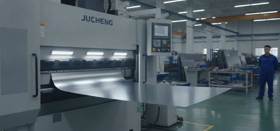
Les logiciels de FAO avancés ingèrent les vecteurs du motif à plat déplié pour générer automatiquement les imbrications de découpe laser et les trajectoires d'outil programmables pour les cintreuses.
Passer directement d'un modèle virtuel validé au code G machine est le summum de l'intégration moderne. conception de tôle Au lieu de saisir manuellement les coordonnées dans les contrôleurs laser, nos programmeurs FAO exportent directement les vecteurs à plat. Le logiciel d'imbrication regroupe étroitement plusieurs pièces sur des tôles standard pour minimiser les déchets de matière première.
Ce flux numérique programme également nos presses plieuses. Le logiciel de FAO lit les lignes de pliage 3D et les facteurs K calculés pour générer des simulations de pliage 3D, en sélectionnant automatiquement le poinçon, la matrice en V et le positionnement de la butée arrière appropriés. Cette génération automatisée de code G minimise les réglages manuels des machines, rendant votre fabrication rapide et hautement répétable.
Téléchargez vos fichiers STEP/IGES 3D chez JUCHENG pour des devis instantanés
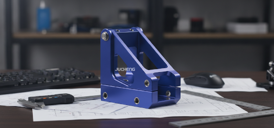
Comment JUCHENG accélère-t-il le cycle de développement des boîtiers prototypes personnalisés ?
Nous ingérons les données de CAO 3D directement dans notre plateforme d'ingénierie automatisée, en vérifiant les tolérances, les rayons de pliage et les dégagements en quelques heures.
Nous éliminons les frictions des cycles de prototypage traditionnels en acceptant des téléchargements directs de fichiers 3D STEP, IGES ou DXF. Notre réseau d'ingénierie utilise des algorithmes de calcul avancés pour analyser instantanément vos modèles CAO, en vérifiant les dégagements entre brides et bords et les risques d'interférence d'outils. Cette traduction numérique se connecte directement à nos lasers à fibre multi-axes et à nos cintreuses, convertissant vos conceptions virtuelles en pièces physiques avec une précision dimensionnelle serrée. En maintenant des normes strictes ISO 9001 et IATF 16949 sur l'ensemble de notre atelier, JUCHENG est un partenaire de fabrication fiable et à haut rendement pour vous aider à faire évoluer vos conceptions personnalisées.
FAQ : Questions critiques sur la conception de tôlerie 3D
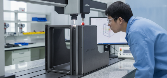
Quelle est la différence entre les fichiers STEP et IGES pour le traitement de la tôlerie ?
Les fichiers STEP sont des modèles solides qui préservent le volume tridimensionnel complet et la structure topologique, ce qui est hautement préféré pour les logiciels de dépliage automatique afin de calculer les déductions de pliage. Les fichiers IGES sont des modèles de surface qui ne définissent que les limites extérieures, ce qui peut parfois entraîner une perte de données géométriques et des erreurs de rendu du motif à plat.
Un programme de CAO 3D peut-il détecter automatiquement les limites de fissuration du matériau ?
Non, les programmes de CAO standard ne vérifient que les jeux géométriques ; ils ne simulent pas les limites de déformation métallurgique. Si vous spécifiez un rayon de pliage intérieur trop petit pour une trempe d'alliage dur, le logiciel rendra un pli 3D parfait. Les concepteurs doivent configurer manuellement leurs paramètres de conception pour maintenir des rapports épaisseur-rayon sûrs.
Pourquoi une table de pliage personnalisée est-elle préférée à un facteur K générique ?
Un facteur K générique suppose un déplacement théorique et uniforme de l'axe neutre, qui varie dans des conditions réelles. Une table de pliage personnalisée utilise des mesures empiriques prises directement à partir de pliages d'essai physiques effectués sur nos presses plieuses d'atelier, garantissant que vos schémas à plat CAO intègrent des compensations d'allongement exactes et spécifiques à la machine.
Comment JUCHENG utilise-t-il les données de conception de tôlerie 3D pour des devis automatisés ?
Notre plateforme de devis automatisé analyse vos fichiers CAO 3D téléchargés pour calculer les longueurs totales de périmètre de coupe, le nombre de plis requis et les rendements de mise en tôle. Cette ingestion numérique nous permet de fournir des estimations de fabrication extrêmement précises et garanties dans les vingt-quatre heures, sans nécessiter de relevés manuels lents.

