


Sheet metal is one route within a broader manufacturing plan. Our Consumer Products manufacturing solutions help teams compare fabrication with CNC machining, injection molding, 3D printing, and other processes according to geometry, quantity, material, finish, and validation needs.
When is sheet metal fabrication a good fit?
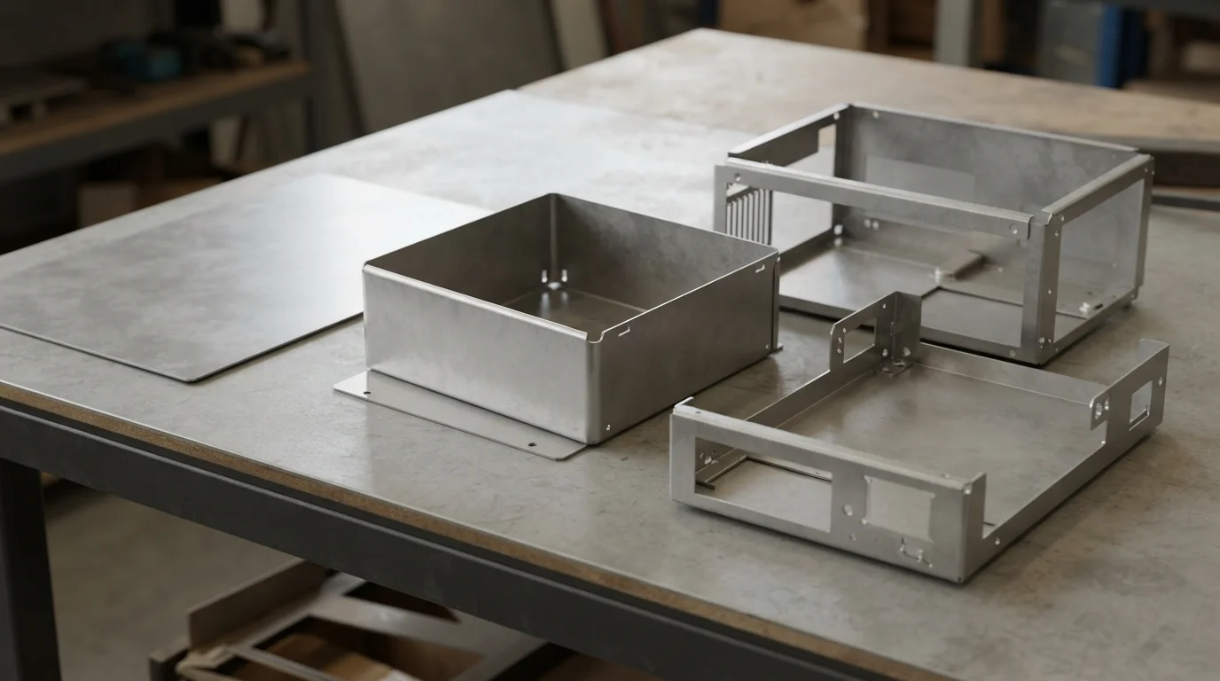
Sheet metal fabrication is often a good fit for products with planar or developable surfaces, bends, cutouts, mounting features, and assemblies made from several formed pieces. Consumer electronics enclosures, appliance panels, equipment covers, brackets, battery housings, protective guards, and compact chassis are common examples of the type of product architecture that may benefit from fabricated metal.
The process can support early prototypes without requiring a dedicated mold. A flat pattern can be laser cut or otherwise processed, then bent, joined, finished, and assembled for evaluation. This lets a team check size, access, stiffness, mounting, ventilation, cable routing, and visual proportions while the design is still changing.
| Product need | Why sheet metal may help | What to confirm |
|---|---|---|
| Protective enclosure | Formed panels can create a rigid shell around internal components. | Clearance, access, seams, fasteners, ventilation, and finish |
| Bracket or support | Bends can add stiffness without machining a solid block. | Load direction, bend position, hole alignment, and assembly |
| Thermal or conductive structure | Metal can provide a useful path for heat or electrical continuity where required. | Material, contact surfaces, grounding, insulation, and environment |
| Prototype chassis | Cut-and-bend fabrication allows rapid geometry and layout changes. | Flat pattern, bend sequence, hardware, and cosmetic expectations |
Sheet metal is not automatically appropriate for every rounded, seamless, or highly sculpted consumer product. If the design depends on complex three-dimensional curvature, integrated snap features, or a continuous molded surface, another process may be more suitable. A hybrid design can also combine a fabricated metal frame with printed, machined, or molded covers.
How should the part be designed for cutting and bending?
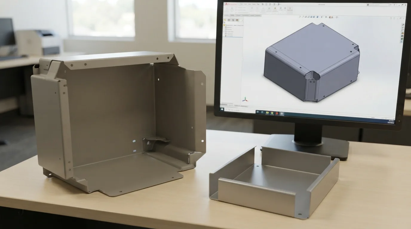
Sheet metal design begins as a flat blank and becomes a three-dimensional part through cutting, bending, forming, joining, and finishing. The 3D model should therefore be checked together with its flat pattern and manufacturing sequence. A shape that looks correct in the assembled model may produce difficult bend access, collisions, distorted holes, or an inaccurate final size.
Key design considerations include:
- Material and thickness: the selected stock affects bend behavior, stiffness, weight, edge condition, and surface finish.
- Bend radius: inside radius should be compatible with the material, thickness, tooling, and required appearance.
- Bend relief: relief features can reduce tearing and distortion where bends meet edges or corners.
- Hole-to-bend distance: holes placed too close to a bend can deform or move during forming.
- Flat-pattern compensation: the blank must account for bend allowance, bend deduction, and the selected process.
- Corner and seam strategy: decide whether corners will remain open, be welded, use hardware, or use a separate cover.
- Hardware access: allow room for inserts, fasteners, tools, cable connectors, and service operations.
Design for assembly is just as important as design for fabrication. Protolabs notes that assembly brings individual fabricated components together into a complete functional enclosure. Review how panels locate, how fasteners are installed, where a gasket sits, and whether the internal parts can be serviced after the enclosure is closed.
For a prototype, prioritize the features that influence product decisions. A bracket may need accurate mounting holes and a defined bend angle, while a cosmetic cover may need a controlled edge, seam, and finish. Avoid applying the same tolerance or finish requirement to every face when the product does not need it.
Which materials, hardware, and finishes matter?
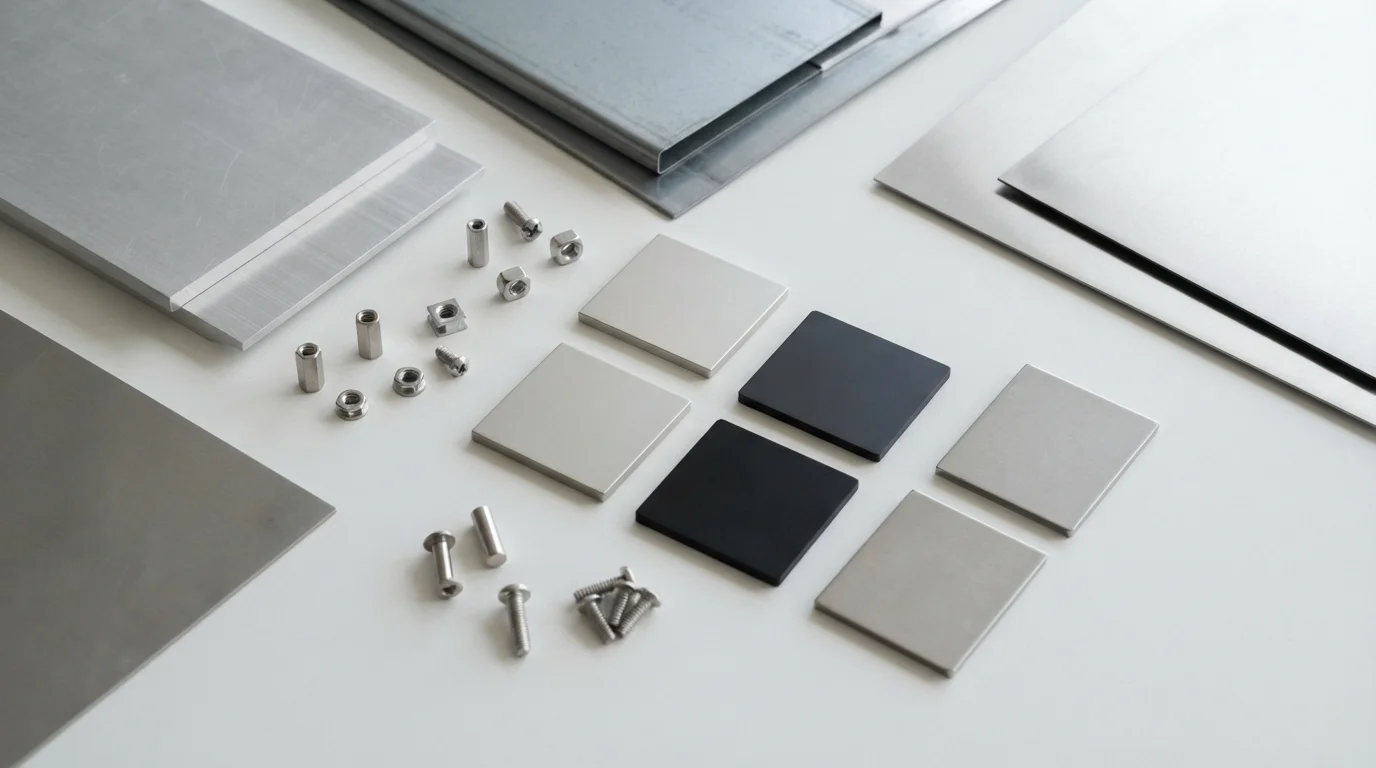
Material selection should follow the enclosure or component’s actual role. Aluminum may be considered where low weight, corrosion resistance, or thermal behavior matters. Steel can provide stiffness and a different cost or finish direction. Stainless steel may suit products exposed to moisture or requiring a particular appearance. The material and temper influence formability, springback, edge quality, weld behavior, and final dimensions.
Do not select a grade from a generic list alone. Confirm the required strength, weight, corrosion resistance, electrical behavior, thermal path, surface appearance, and operating environment. If the enclosure must support sensitive electronics, the design may also require a considered approach to grounding, shielding, ventilation, insulation, and access. Such requirements need project-specific review rather than an assumed performance claim.
| Design decision | Questions to ask | Potential consequence |
|---|---|---|
| Material and thickness | What stiffness, weight, corrosion, temperature, and finish are needed? | Changes forming, springback, joining, cost, and handling |
| Quincaillerie | Will the assembly use tapped holes, self-clinching hardware, rivets, weld nuts, or screws? | Influences access, thread strength, serviceability, and sequence |
| Finition | Is the surface painted, powder coated, anodized, plated, brushed, or left natural? | Can alter appearance, edge coverage, dimensions, and masking needs |
| Joining | Will parts be welded, riveted, screwed, bonded, or mechanically interlocked? | Affects distortion, visible seams, strength, and rework |
Finishing is part of the product design, not a final cosmetic afterthought. Define which surfaces are visible, handled, grounded, masked, sealed, or protected from wear. A sample panel or approved reference can make color and texture reviews more consistent than subjective descriptions.
Hardware should be designed into the assembly early. Inserts, standoffs, hinges, clips, cable glands, and captive fasteners may require access holes, clearances, or local reinforcement. If the product will be opened for service, consider repeated fastening and the risk of damaging threads or coatings.
How should fit, appearance, and performance be validated?
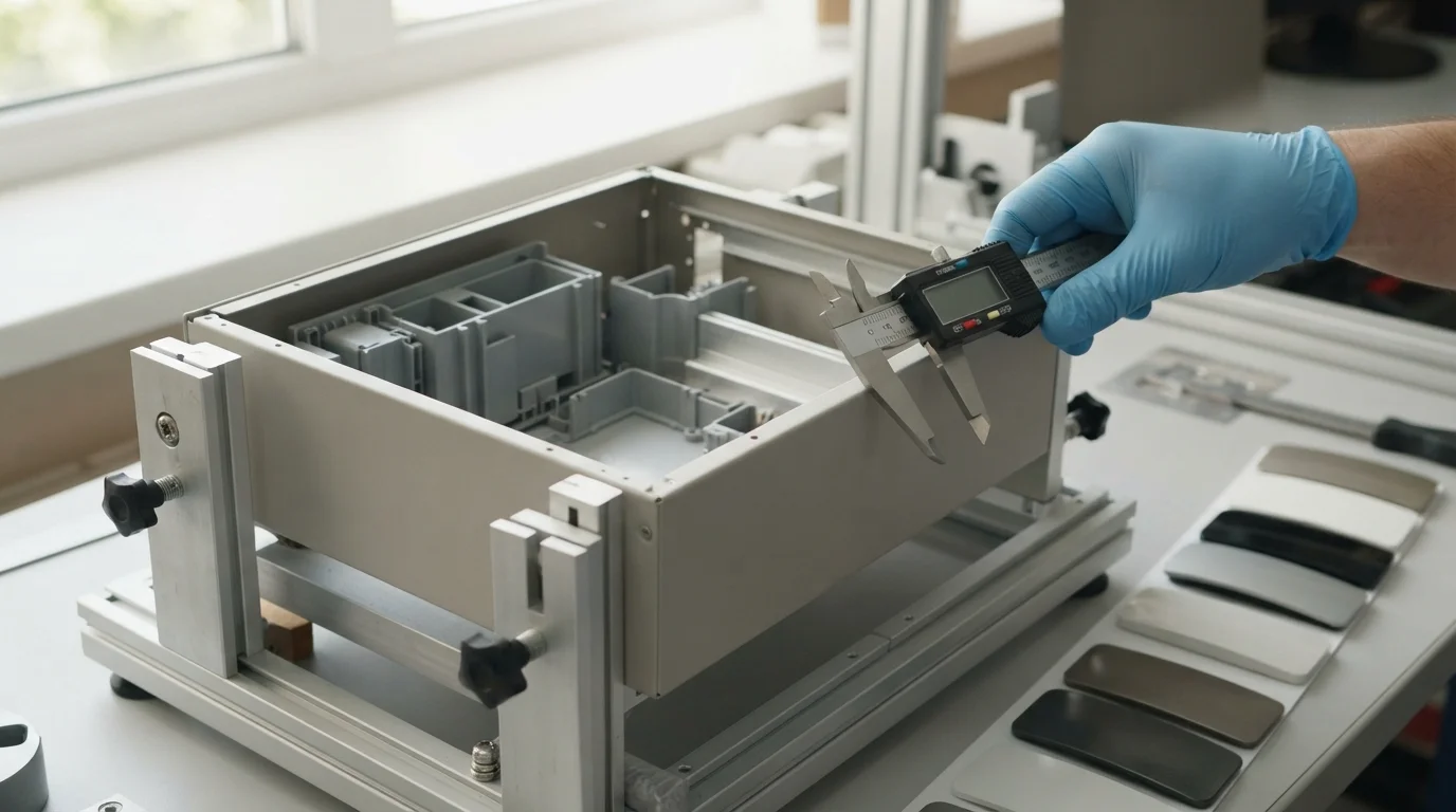
A sheet metal prototype should be evaluated as a complete assembly. Checking only the formed shell can miss conflicts with PCBs, batteries, cables, fans, displays, connectors, seals, or adjacent covers. Provide the internal components or accurate reference geometry whenever they affect fit and function.
Validation can progress through several reviews:
- Dimensional review: check overall envelope, mounting holes, bend locations, openings, and critical datums.
- Assembly review: install hardware and internal components, then record interference, access, sequence, and service issues.
- Performance review: evaluate stiffness, vibration response, heat paths, shielding or grounding requirements, and environmental exposure as appropriate.
- Appearance review: inspect seams, corner transitions, bend marks, welds, fasteners, texture, color, and visible edges under representative lighting.
- Revision review: connect every finding to the CAD model, drawing, flat pattern, process, or assembly instruction.
Sheet metal can show process-specific variation. Bending may create springback; welding can introduce distortion; finishing can affect dimensions and edge coverage; hardware installation can change flatness or local stiffness. The prototype should identify which variations matter to the product, not promise that all fabricated parts will behave identically without a defined process and inspection plan.
Use a reference sample for cosmetic approval and a drawing or fixture for functional approval. This separation helps the team avoid rejecting a functionally correct part because of an unimportant hidden mark, or approving an attractive part whose mounting or service access is still unresolved.
How does fabrication scale from prototype to production?
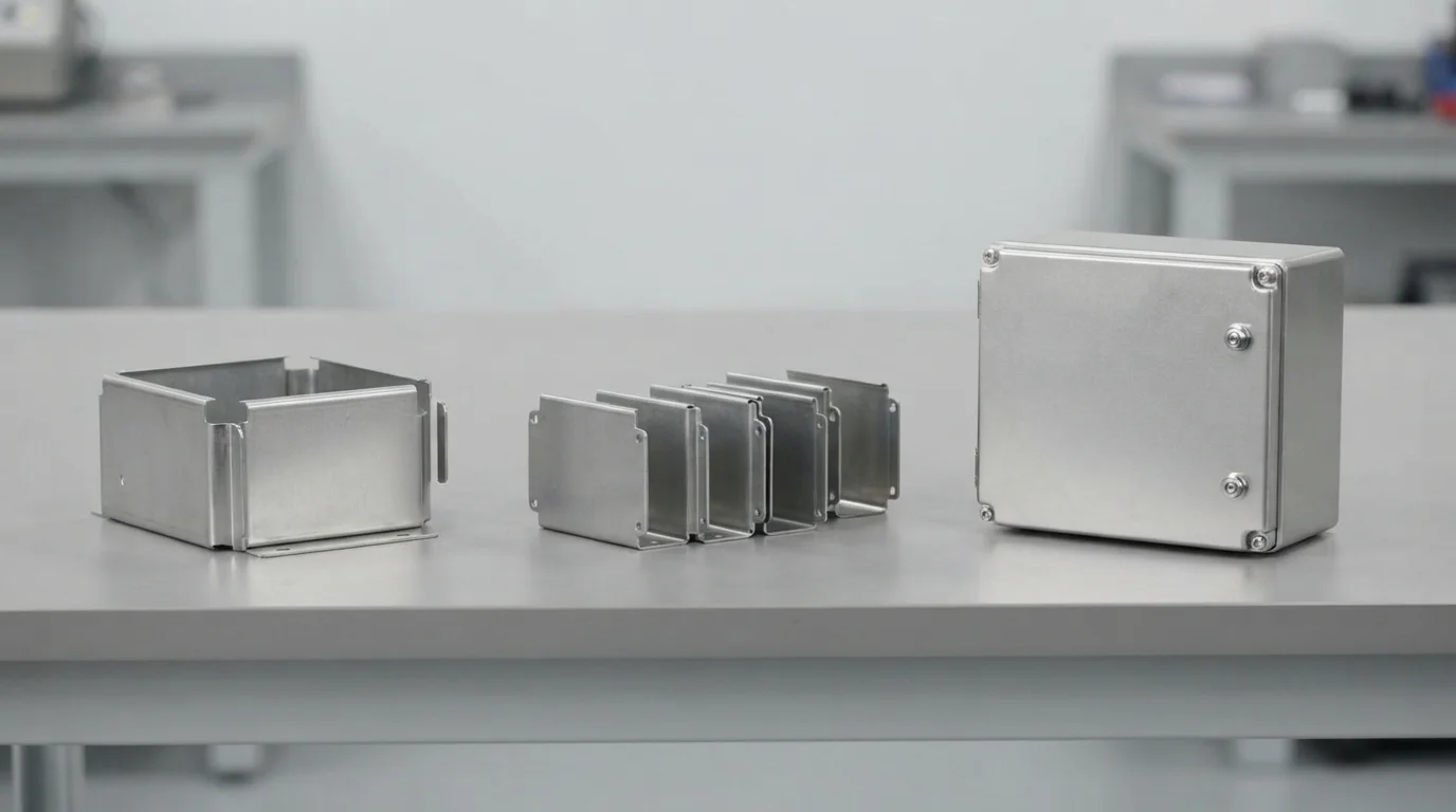
Sheet metal fabrication can move from one-off prototypes to small batches and repeat production, but the design and process definition must become more controlled as quantity increases. A prototype may be manually adjusted during assembly; repeat production needs an approved flat pattern, bend sequence, hardware specification, finish standard, and inspection method.
A practical transition includes:
- Freeze the current CAD, drawings, material, thickness, finish, and hardware assumptions.
- Review flat patterns, bend allowances, tooling access, corner reliefs, holes, and joining methods.
- Build and inspect the first prototype or engineering sample in the intended material direction.
- Resolve fit, appearance, assembly, and performance findings through controlled revisions.
- Produce several consistent parts to evaluate repeatability, assembly time, finish, and packaging.
- Define the production baseline, inspection points, cosmetic reference, and change-control process.
Notre sheet metal fabrication service can be considered for this staged workflow. The correct route still depends on the part’s size, material, thickness, geometry, quantity, finish, and quality requirements. When the design includes machined interfaces or printed fit models, a cross-process plan may reduce risk.
Do not assume that the cheapest prototype construction is the best production method. A welded assembly may be useful for early validation but require a different approach when repeatability, cosmetic consistency, or assembly time becomes more important. Conversely, a simple formed part may remain practical from prototype through a low-volume run.
What should a sheet metal RFQ include?
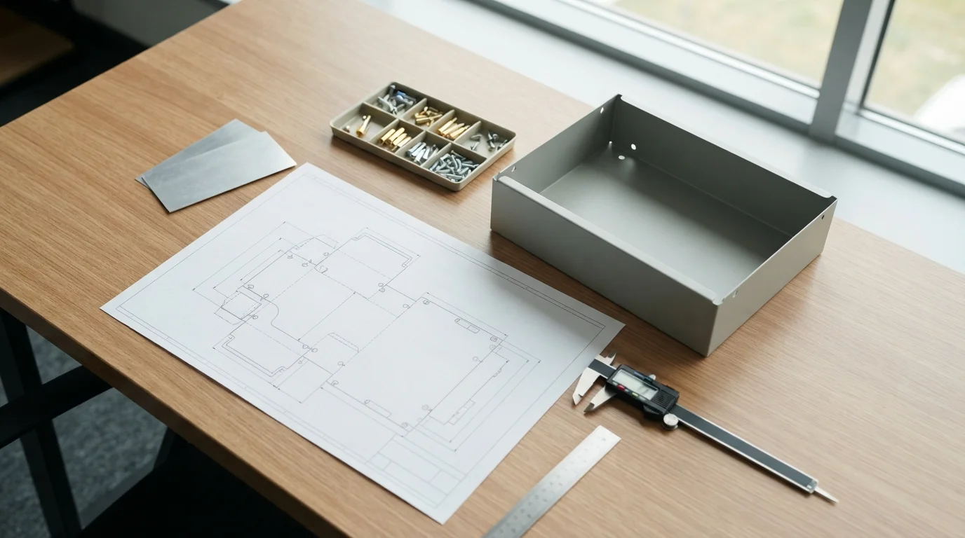
A clear RFQ lets a fabricator review both the geometry and the intended product stage. Provide the information needed to estimate cutting, bending, forming, joining, finishing, hardware, inspection, and assembly rather than sending only an incomplete 3D model.
| RFQ item | Information to provide |
|---|---|
| Product context | What the part protects or supports, user environment, loads, access, and prototype objective |
| Files | 3D CAD, flat pattern if available, 2D drawings, assembly context, and current revision |
| Matériau | Grade or performance target, thickness, temper, approved alternatives, and compliance needs |
| Fabrication | Cutouts, bends, forming, welds, rivets, inserts, fasteners, and assembly sequence |
| Finition | Color, texture, coating, masking, cosmetic surfaces, and reference sample |
| Quantity | Prototype count, design iterations, pilot quantity, and possible follow-on volume |
| Qualité | Critical dimensions, datums, inspection evidence, functional checks, and cosmetic criteria |
| Schedule | Design review, first sample, feedback cycle, pilot build, and production decision |
Frequently asked questions
Is sheet metal suitable for consumer product prototypes?
Yes, when the product benefits from formed metal geometry, stiffness, service access, shielding, thermal behavior, or a metal appearance. If the design is highly sculpted or depends on molded features, another process or a hybrid prototype may be more appropriate.
What is the difference between a sheet metal prototype and a production part?
The prototype may use a flexible fabrication and assembly approach to answer design questions quickly. A production part requires a controlled material, flat pattern, bend process, joining method, finish, inspection plan, and repeatability target. The two can be similar, but the production definition must be verified.
Should the flat pattern be included in a sheet metal RFQ?
Include it when it has been reviewed and is part of the current design. If the flat pattern is not final, send the 3D model and drawings and ask the manufacturer to review the unfolding assumptions. The result should remain tied to the selected material, thickness, bend method, and tooling.
Consumer product sheet metal fabrication works best when the product is designed as both a formed part and an assembled system. Define the material, bends, hardware, finish, and validation goal early; then use prototype feedback to improve the design before repeat production. This approach helps the team balance appearance, stiffness, serviceability, cost, and manufacturing feasibility.

