


L'usinage de moules massifs en acier trempé à plusieurs cavités nécessite des mois d'heures de précision par électroérosion et des investissements en capital importants difficiles à justifier lors des lancements de produits précoces. L'approvisionnement d'inserts de noyau et de cavité en aluminium représente une solution de transition très efficace, permettant aux groupes de mécatronique de produire des milliers de pièces en plastique fonctionnelles à partir de résines de qualité production. L'outillage en aluminium QC-10 ou en acier doux P20 est fabriqué en une fraction du temps nécessaire pour les outils durs traditionnels en H13, accélérant les délais de mise sur le marché. Les évaluations structurelles réelles nécessitent des pièces qui se comportent exactement comme la production en série, faisant du moulage par injection rapide l'étape ultime avant la mise à l'échelle.
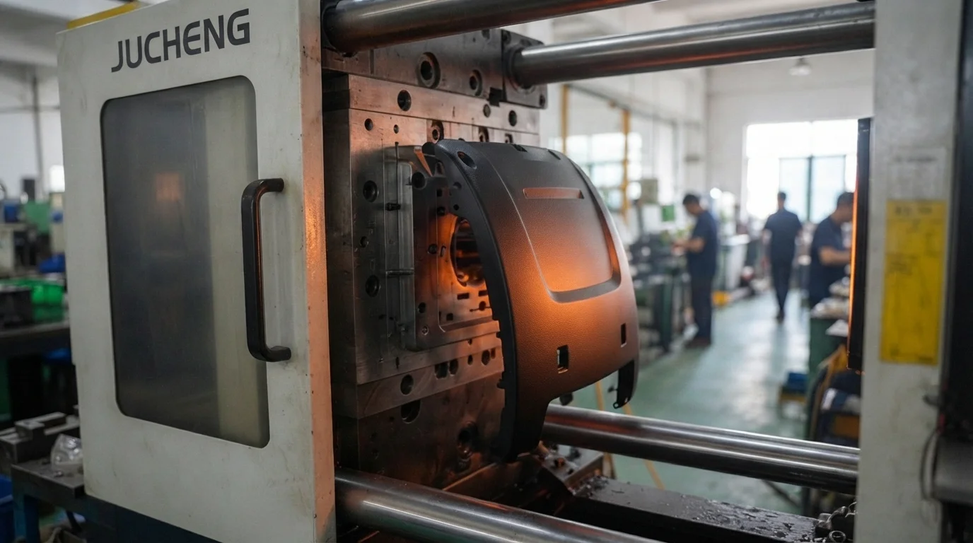
La mise en œuvre réussie des conception de prototypage rapide principes nécessite des plans de transition qui anticipent les limitations physiques réelles du moulage par injection dès le début du processus de modélisation CAO. De nombreuses équipes d'ingénierie négligent les angles de dépouille, les fermetures de ligne de joint et les positions des éjecteurs lors de la modélisation spatiale initiale, entraînant des reprises d'outillage coûteuses. Les logiciels de simulation d'écoulement de moule permettent aux spécialistes de l'outillage de prédire le cisaillement localisé du polymère, les poches d'air et les lignes de soudure des matériaux avant de couper le métal brut. La résolution de ces défauts de remplissage et d'éjection garantit que les pièces de courte série se démoulent proprement des cavités sans rayures ni déformations.
L'approvisionnement de pièces moulées par injection de courte série permet aux groupes de développement d'effectuer des évaluations fonctionnelles réglementaires, environnementales et mécaniques sur des résines de qualité production. Les nylons chargés de verre, les polycarbonates résistants aux chocs et les polymères biocompatibles sont moulés sous des forces de serrage élevées pour vérifier les limites de fatigue réelles. Les concepteurs d'outillage optimisent les dispositions des canaux d'eau de refroidissement dans les blocs métalliques doux pour maintenir des températures de cavité uniformes pendant les cycles rapides. Un contrôle de processus méticuleux empêche le gauchissement des pièces, garantissant que les caractéristiques d'emboîtement s'assemblent parfaitement sur chaque lot moulé.
Table des matières
1. Physique du transfert de chaleur des cavités en métal doux et de l'outillage rapide
2. Lignes de joint, emplacements des points d'injection et placements des éjecteurs
3. Exigences de dépouille et mise à l'échelle structurelle pour grand volume
Cavités en métal doux et physique du transfert de chaleur de l'outillage rapide
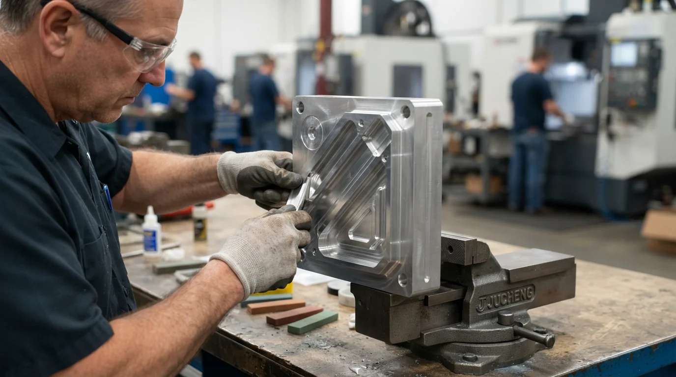
Question : Pourquoi les moules en aluminium refroidissent-ils plus vite que l'outillage en acier ? L'aluminium présente des valeurs de conductivité thermique jusqu'à quatre fois supérieures à celles de l'acier à outils P20 standard, ce qui entraîne des temps de cycle de refroidissement plus courts.
Le choix des métaux bruts pour les moules influence directement les temps de cycle de moulage par injection et la stabilité dimensionnelle globale des pièces pendant les séries de production. Le respect des directives de conception d'outillage rapide éprouvées garantit que les ingénieurs sélectionnent de l'aluminium QC-10 de haute qualité ou de l'acier doux P20 pour construire des plaques de moule rentables. La conductivité thermique supérieure de l'aluminium dissipe rapidement la chaleur des polymères fondus, réduisant considérablement la durée de la phase de refroidissement. Des cycles de refroidissement plus courts minimisent les contraintes internes localisées, empêchant les parois minces en plastique de se déformer lors de l'éjection de la pièce.
Les cavités en aluminium QC-10 sont usinées à l'aide de centres de fraisage CNC à grande vitesse, éliminant plusieurs configurations d'électroérosion et accélérant les délais de livraison. Les cavités en métal doux traitent efficacement les résines modifiées chargées de verre pour des séries de production moyennes de 10 000 à 100 000 composants en toute sécurité. L'approvisionnement de blocs d'outillage en aluminium réduit les dépenses initiales de moule jusqu'à 70 % par rapport aux moules de production traditionnels. Les concepteurs d'outillage analysent tôt les séparations de ligne de joint pour garantir que les fermetures en aluminium doux résistent à l'usure sous des pressions de serrage élevées.
L'exploitation des moules à des températures de cavité stables nécessite l'intégration de canaux d'eau de contrôle thermique précis directement dans les noyaux du moule. Les canaux de refroidissement conformes usinés sur des machines CNC multi-axes suivent les contours complexes des pièces, maintenant une uniformité de refroidissement absolue. Une réduction thermique constante empêche les hubs épais en polymère ou les bossages de vis solides de rétrécir de manière inégale. L'élimination des contraintes de retrait inégales empêche l'apparition de marques de retrait inesthétiques sur les faces visibles.
Lignes de joint, emplacements des points d'injection et placements des éjecteurs
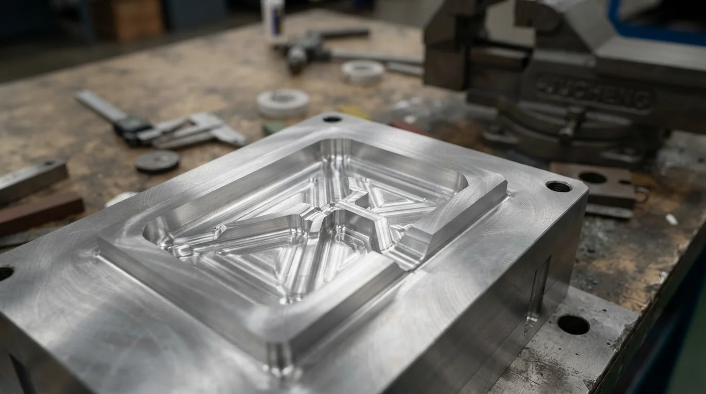
Question : Où les points d'injection doivent-ils être situés sur les boîtiers cosmétiques ? Positionner les points d'injection sur les faces cachées inférieures ou sur les structures de nervures internes masque les marques de cisaillement et préserve l'esthétique extérieure.
Le plastique fondu entre dans la cavité du moule par des points d'injection précis, laissant une marque fine et visible qui doit être ébarbée à la main ou poncée à ras. Les concepteurs d'outillage positionnent les points d'injection en bordure, les sous-points d'injection ou les buses de canal chaud sur des surfaces non cosmétiques pour protéger l'esthétique visuelle. Le cisaillement du polymère est fortement concentré aux entrées des points d'injection, ce qui rend le dimensionnement correct des points d'injection essentiel pour éviter les défauts cosmétiques. L'obtention de simulations complètes d'écoulement de moule aide les ingénieurs à déterminer les emplacements optimaux des points d'injection avant de découper les blocs de noyau en acier brut.
Les éjecteurs poussent physiquement la pièce en plastique solidifiée hors du noyau du moule, laissant des marques circulaires peu profondes sur la surface du polymère. Placer les éjecteurs sur les faces intérieures des bossages, les jonctions de nervures structurelles ou les parois inférieures non visibles protège les surfaces d'apparence cosmétique. Les concepteurs d'outillage équilibrent la disposition des éjecteurs symétriquement autour des géométries complexes pour éviter la torsion de la pièce ou le blanchiment sous contrainte lors de l'éjection. Un placement symétrique des éjecteurs assure une libération uniforme de la pièce du noyau sans micro-fissures.
L'application méticuleuse des directives de conception d'outillage rapide garantit que les lignes de joint sont planifiées le long de limites géométriques naturelles et nettes. Le polymère fondu sous haute pression d'injection peut s'échapper le long des lignes de séparation, formant des bavures de plastique minces qui nécessitent un ébavurage manuel. Les fermetures de ligne de joint doivent être ajustées à la main avec précision pour empêcher la formation de bavures sur les joints d'accouplement critiques. Ce tableau de comparaison technique met en évidence les différences de matériaux et d'outillage entre les normes de moule de base :
| Matériau d'outillage | Conductivité thermique | Durée de vie typique de l'outil | Application d'outillage principale |
|---|---|---|---|
| Aluminium QC-10 | 160 W/m·K | 10 000 à 100 000 cycles | Moulage de transition à délai rapide, plastiques à faible volume |
| Acier P20 doux | 30 W/m·K | 100 000 à 500 000 cycles | Boîtiers de consommation de volume moyen, résines modifiées chargées de verre |
| Acier H13 dur | 24 W/m·K | Plus de 1 000 000 de cycles | Production de masse multi-empreintes, polymères hautement abrasifs |
L'intégration d'actions latérales coulissantes ou de vérins mécaniques permet aux pièces avec des contre-dépouilles externes complexes de se libérer proprement sans déchirure. Les tiroirs de noyau se déplacent le long d'axes de coordonnées séparés lorsque le moule se sépare, ajoutant une complexité mécanique à l'outillage. La conception de lignes de séparation simples ou de fermetures coulissantes élimine ces mécanismes supplémentaires, réduisant les heures de fabrication de l'outillage.
Exigences de dépouille et mise à l'échelle structurelle pour un volume élevé
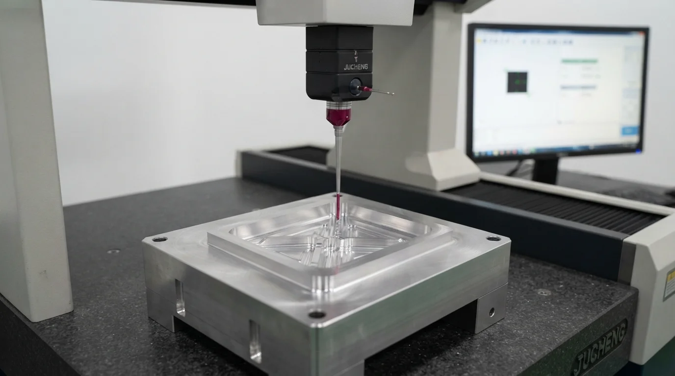
Question: What is the minimum recommended draft angle for quick-turn injection molds? Incorporating a draft angle of 1.5 degrees on all vertical features allows molded plastic to slide free easily.
Vertical features like reinforcing ribs and bosses must taper slightly to allow parts to release from core cavities cleanly. Zero-draft walls drag against core steel under high shrinkage pressures, creating visible scuff marks and deep stress cracks. Incorporating a minimum draft angle of 1.5 degrees on all vertical features allows molded plastic to slide free easily. Specialized textured finishes may demand up to 3 degrees of draft to prevent dragging against the mold cavities.
Applying these rigid rapid tooling design guidelines ensures that your prototype parts perform exactly like series-production injection molded components. Jucheng Precision operates a fully equipped manufacturing facility containing 150+ CNC machines and 35 precision injection presses. Sourcing early analyses DFM gratuites 24h/24 analyses helps product groups optimize gate placements, parting lines, and draft profiles before pouring silicone or milling metal. Sourcing high-fidelity pre-production parts prevents tooling reworks and protects launch budgets.
Flexible manufacturing programs with no minimum order requirements allow design groups to iterate custom hardware over multiple small-batch runs safely. Specialized l'outillage rapide molds deliver high-quality injection-molded components within 4 to 15 days, helping design groups hit aggressive launch schedules. Operating under a strict no-MOQ policy enables mechatronics groups to refine customized hardware variations safely. Sourcing your prototypes from a certified manufacturer ensures your designs transition smoothly from early concept models to mass series production.
Foire aux questions (FAQ)
Can aluminum rapid tooling molds handle modified glass-filled resins?
Aluminum rapid molds utilizing QC-10 or highly wear-resistant alloys handle glass-filled resins efficiently for medium runs of 10,000 to 100,000 parts. Tooling components are designed with robust gate locations to minimize fiber shearing during injection.
How is part warpage prevented during rapid injection molding?
Maintaining uniform wall thicknesses is the primary method to prevent differential shrinkage and post-mold part warpage. Integrating balanced cooling lines within the aluminum cavity blocks ensures even heat transfer across all part features.
What is the typical lead time for an aluminum rapid tooling mold?
Aluminum rapid molds are machined quickly on multi-axis CNC mills, typically taking only 10 to 15 business days to complete. Bypassing slow spark-erosion EDM processes allows manufacturers to deliver functional molded samples within weeks.

