


A fuel cell end plate does more than close the stack. It distributes clamping load, limits bending, supports ports and tie rods, protects fragile internal layers, and often provides the mounting interface to the surrounding system. A poor material choice can create uneven gasket pressure even when the plate looks strong.
Choosing fuel cell end plate materials therefore begins with stiffness, corrosion, electrical isolation, weight, machining, and assembly—not tensile strength alone. The geometry and preload strategy decide how those properties are used.
The End Plate Is a Load-Distribution Component
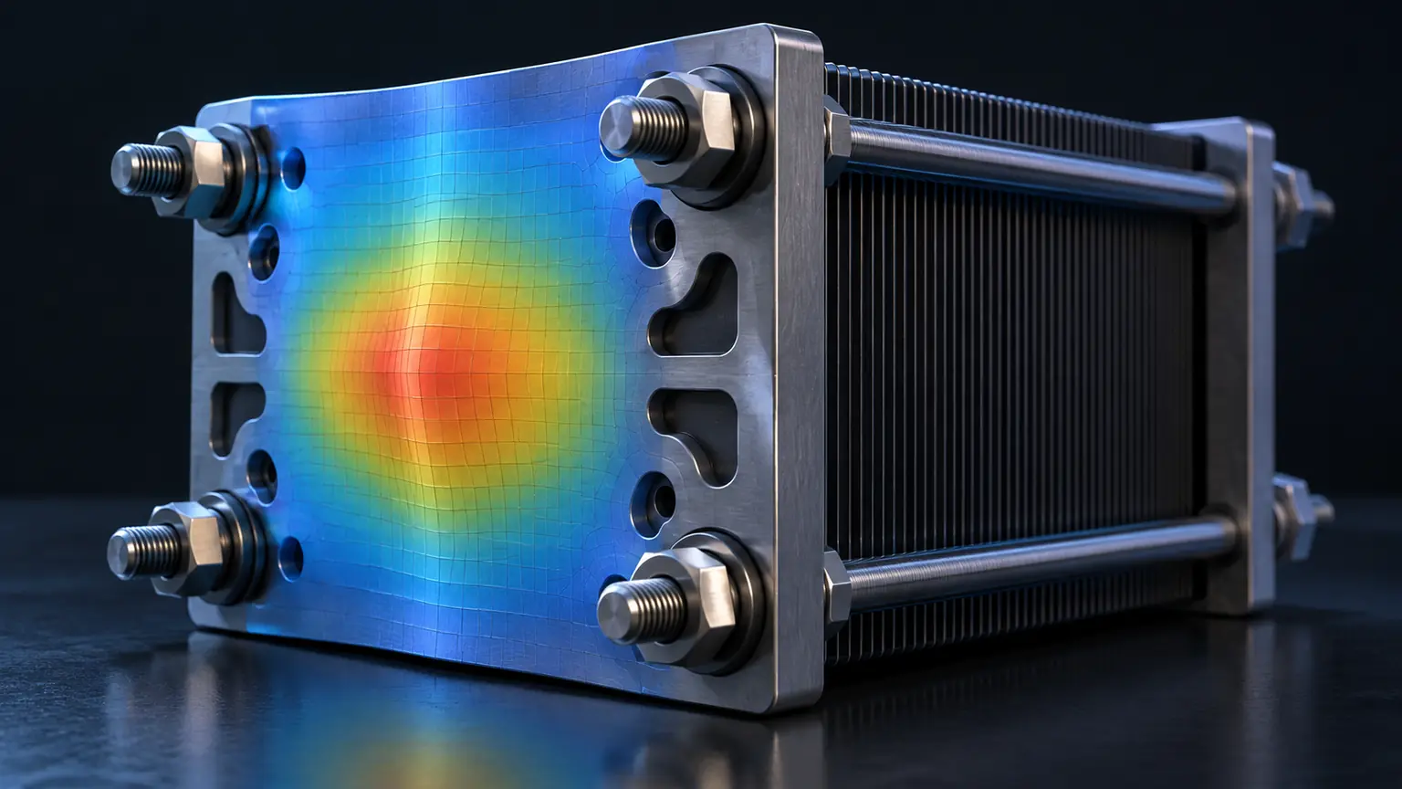
Stack preload enters through bolts, tie rods, bands, or a frame. The end plate spreads that force over the active area. If it bends, pressure rises near the fasteners and falls toward unsupported regions. That can change electrical contact, gasket compression, membrane loading, and leakage behavior.
Stiffness depends strongly on thickness, span, rib geometry, boundary conditions, and elastic modulus. Increasing material strength does not automatically reduce elastic deflection. A high-strength but flexible layout may still bow more than a lower-strength material in a better section.
Four Material Families, Four Different Compromises
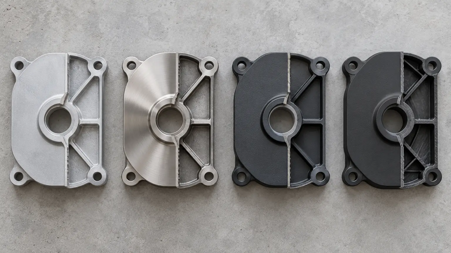
Aluminum alloys: low mass and easy machining
Aluminum is widely considered for prototypes and mobile systems because it is lightweight, machinable, and available in plate form. Ribs, pockets, ports, and mounting features can be integrated into one part. Its lower elastic modulus compared with steel means the design may need greater thickness or deeper ribs to achieve the same stiffness.
Corrosion exposure, coolant contact, electrical conductivity, anodizing or coating, threaded insert strategy, and galvanic interfaces require review. For complex prototypes, usinage CNC allows fast iteration of rib patterns, preload features, and manifold interfaces.
Stainless steel: stiffness and environmental durability
Stainless steel provides higher stiffness and useful corrosion resistance, but mass and machining cost rise. It can suit stationary systems, compact plate envelopes, or harsh environments where weight is less critical. Grade, finish, passivation, chloride exposure, and contact with other metals still matter.
Coated carbon steel: economical structural capacity
Carbon steel is strong, stiff, economical, and familiar to fabricators. It can work well when a reliable coating system protects the relevant surfaces. Edges, threads, scratches, fastener interfaces, and areas hidden after assembly are common corrosion concerns.
Engineering polymers and composites: isolation with creep questions
Fiber-reinforced polymers and composite structures can reduce mass and provide electrical isolation. Their properties are directional, temperature dependent, and sensitive to moisture, molding quality, inserts, and long-term creep. A short room-temperature compression test cannot prove years of preload retention.
Material Choice Becomes Visible at the Interfaces
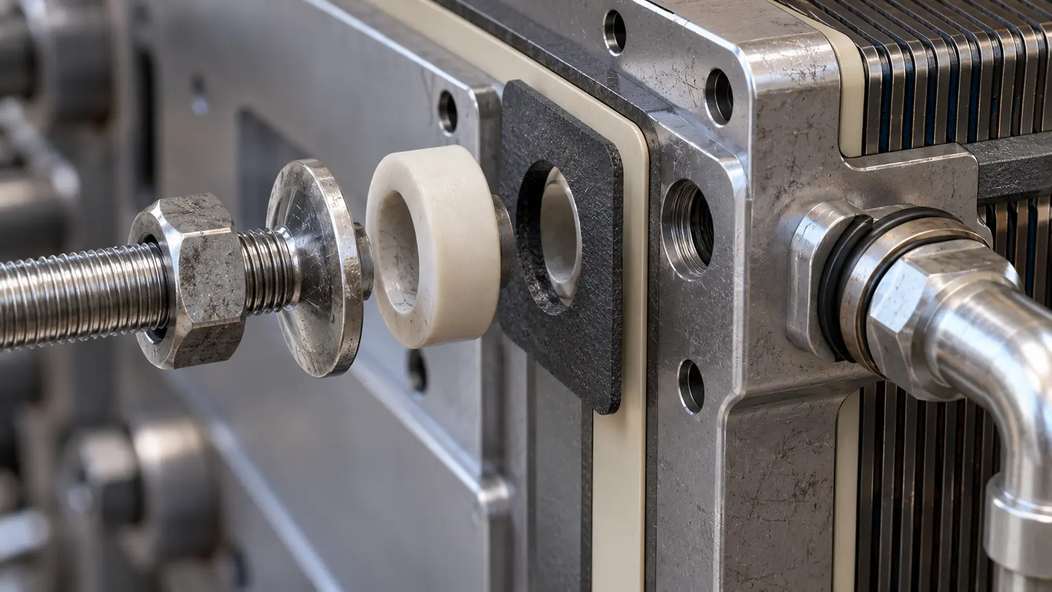
The stack side may contact an insulating sheet, current collector, manifold seal, gasket, or bipolar plate. Each interface needs compatible flatness, finish, hardness, chemical resistance, and pressure. Burrs or local high spots can damage softer layers even when overall flatness passes.
Ports and fittings add concentrated loads and leak paths. Threads in aluminum may need inserts or adequate engagement. Polymer ports may creep under fitting load. Stainless fittings against aluminum create a galvanic pair if moisture is present. The drawing should identify the sealing mechanism and load path rather than merely call out a hole size.
Electrical isolation must be deliberate. An insulating coating can be damaged by a washer or sharp edge; a polymer plate can still conduct through metal inserts or coolant fittings. Grounding and isolation requirements should be verified on the assembled stack.
Functional coatings, anodizing, passivation, or powder coating should be selected with the base material and contact areas. Jucheng Precision’s surface finishing services can coordinate masking, cosmetic zones, sealing lands, and electrical contact requirements with the machined part.
Lightweighting Works Best When Material Follows the Load
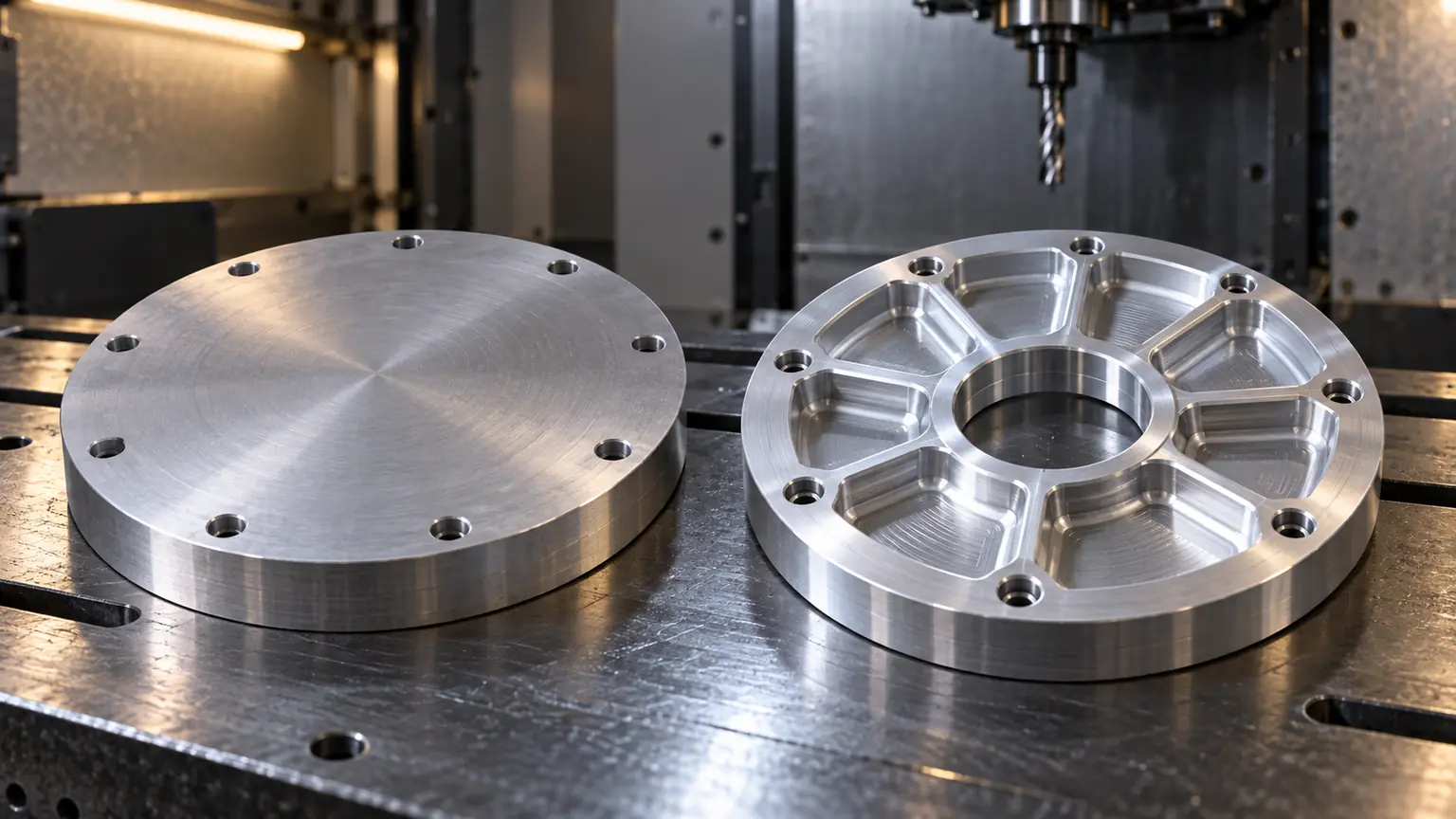
Removing material uniformly is rarely optimal. Keep section depth and load paths near fasteners, support the active-area span with ribs, and preserve material around ports and mounting points. Avoid pockets that trap water or create inaccessible finishing areas.
Deep pockets reduce mass but increase machining time, tool reach, and distortion risk. Thin residual walls can move after unclamping or finishing. A topology-inspired pattern may look efficient in simulation but be expensive to machine and difficult to clean. Simplify ribs into tool-accessible features where performance allows.
A practical lightweighting sequence
- Model preload and operating loads with realistic boundary conditions.
- Define no-cut zones around seals, ports, threads, and mounting interfaces.
- Remove material from low-stress regions while preserving section depth.
- Check machining access, cutter reach, corner radii, and fixturing.
- Measure free-state flatness before and after finishing.
- Confirm stack pressure distribution in a representative assembly.
Three Prototype Builds Answer Different Questions
The stiffness plate
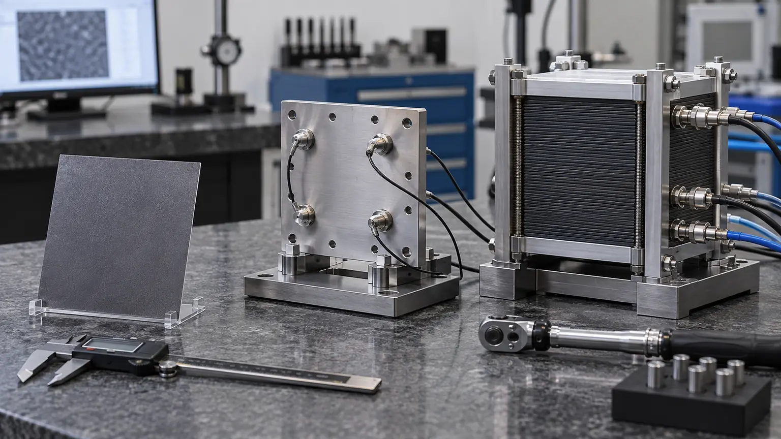
Use economical material and simplified interfaces to validate deflection, rib layout, tie-rod spacing, and assembly preload. Instrument or pressure-map the stack if the test plan allows.
The interface plate
Include production-intent ports, seal lands, inserts, insulating features, and surface finish. This build focuses on leakage, electrical isolation, fitting loads, and assembly handling.
The system plate
Combine final material intent, lightweighting, coatings, mounts, and adjacent hardware. The goal is to expose tolerance stack-up and service problems before a pilot lot. A mixed-process prototype build can include end plates, manifolds, brackets, housings, and test fixtures under one datum review.
What an End Plate RFQ Should Make Explicit

| Information | Why it changes the quote |
|---|---|
| Material grade and condition | Controls machining, strength, finish, and sourcing |
| Preload and support pattern | Defines structural purpose and critical zones |
| Free-state flatness and datum | Changes fixture, sequence, and inspection |
| Sealing and port details | Drives surface finish, grooves, and testing |
| Coating and masked areas | Affects dimensions, handling, and secondary processing |
| Prototype purpose and quantity | Determines the economical manufacturing route |
Short Answers for Design Reviews

Which end plate material is lightest?
Polymers and composites can be very light, while aluminum offers a common balance of low density, stiffness through geometry, and machinability. The complete plate design determines the final mass.
Is stainless steel always stiffer than aluminum?
At equal geometry, steel’s higher elastic modulus generally produces less deflection. Aluminum can recover stiffness through thickness and ribs, often with lower overall mass.
Can an end plate also contain coolant or gas passages?
Yes, but integrated passages add sealing, cleanliness, corrosion, pressure-test, and inspection requirements. The benefit should justify the added manufacturing risk.
When should a machined prototype use the production material?
Use production-intent material when testing corrosion, coating, preload retention, thermal behavior, threads, or other material-dependent performance. Earlier geometry builds may use a practical substitute if clearly documented.
A Good End Plate Makes Preload Predictable
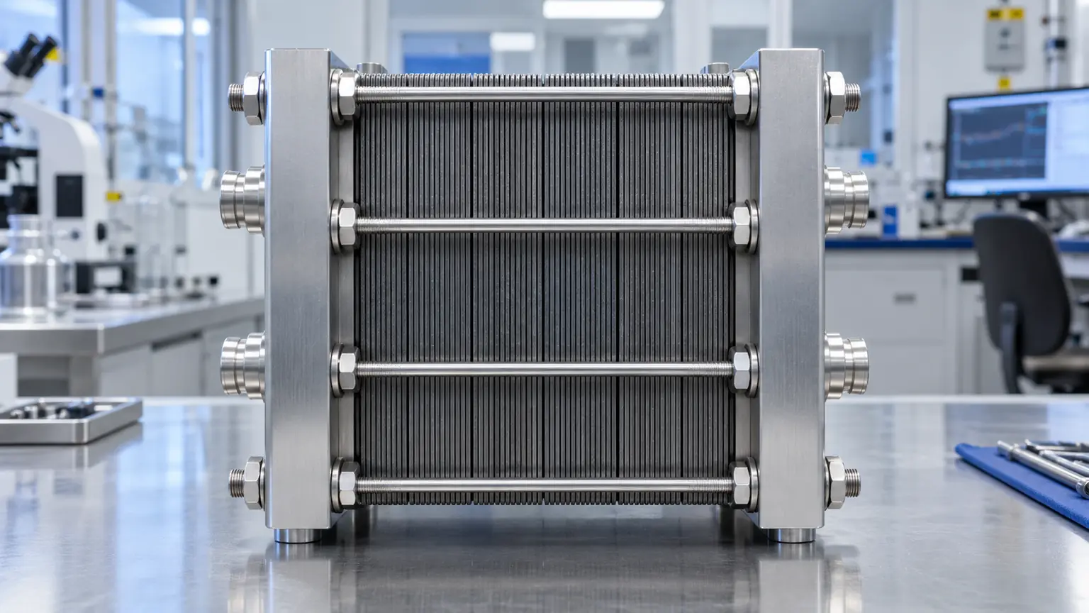
The best fuel cell end plate material is the one that distributes load, survives the environment, controls electrical interfaces, and can be manufactured repeatedly at the target volume. Start with stack mechanics; the right alloy, steel, or composite becomes much easier to justify.

