


Écraser un prototype en plastique avec un marteau lourd parce que les ergots de montage internes refusent de glisser dans les trous désignés du châssis est un rite de passage angoissant pour les ingénieurs. Livrer des composants physiques qui échouent violemment à s'accoupler parfaitement sur la chaîne d'assemblage finale détruit instantanément les calendriers de lancement serrés de l'entreprise. Les responsables des achats interrogent constamment notre équipe d'ingénierie au sujet des tolérances d'impression 3D FDM, cherchant désespérément des garanties mathématiques avant d'émettre des bons de commande.
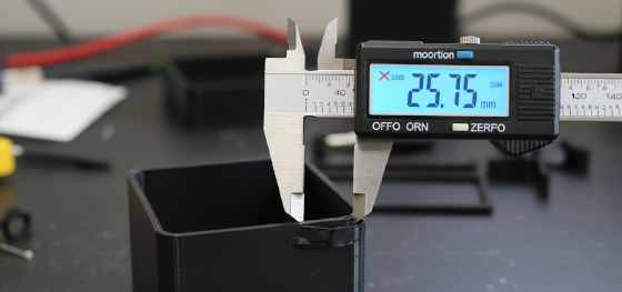
Répondre à cette question critique de fabrication nécessite de dépouiller brutalement les statistiques marketing gonflées publiées par les vendeurs de machines de bureau. S'attendre à une précision de quelques microns directement depuis un plateau de construction en verre chauffé ignore complètement les réalités thermodynamiques violentes de la fusion de polymères industriels. L'extrusion d'ABS fondu ou de polycarbonate rigide introduit intrinsèquement un retrait physique massif lorsque le matériau revient violemment à température ambiante.
Exécuter des assemblages mécaniques impeccables oblige les équipes matérielles à maîtriser des algorithmes avancés de compensation de retrait thermique bien avant d'allumer la buse chauffée. Les concepteurs doivent agressivement surdimensionner les trous internes critiques ou délibérément épaissir les parois externes porteuses pour lutter fortement contre cette contraction chimique inévitable. Ne pas respecter cette métallurgie physique fondamentale garantit des désalignements catastrophiques lors de votre phase de test bêta coûteuse.
Opérant depuis le hub agressif de fabrication de précision de Shenzhen, les vétérans chevronnés apprennent que la fabrication additive pure est souvent insuffisante pour les exigences de qualité aérospatiale. Atteindre une perfection mécanique absolue dicte fréquemment le déploiement de tolérances de fabrication hybrides lourdes pour franchir la ligne d'arrivée. Nous devons impitoyablement décomposer exactement où l'extrusion en couches réussit et où les opérations secondaires soustractives deviennent absolument obligatoires pour la survie du projet.
contenu :
Surmonter les limitations sévères de retrait thermique
Vaincre la compression de l'axe Z et le pied d'éléphant
Survivre au cauchemar des trous ovales pour roulements
Hub JUCHENG : Dominer les capacités hybrides
Questions fréquemment posées : Réalité dimensionnelle
Surmonter les limitations sévères de retrait thermique

Est-ce que tous les filaments polymères industriels rétrécissent exactement de la même quantité après avoir quitté la buse chauffée ?
Absolument pas. Les matériaux techniques haute température subissent une contraction thermique massive par rapport aux plastiques d'entrée de gamme standard, nécessitant des multiplicateurs d'échelle entièrement différents pour atteindre correctement les tolérances d'impression 3D FDM ciblées.
Traiter avec des parois géométriques épaisses emprisonne intrinsèquement d'énormes quantités de chaleur thermique au plus profond du noyau plastique. Pendant que la peau extérieure imprimée refroidit et durcit rapidement contre l'air ambiant de l'usine, le centre en fusion continue de rétrécir lentement pendant plusieurs heures. Ce différentiel de température interne sévère tire physiquement les parois externes vers l'intérieur, créant des surfaces concaves disgracieuses qui ruinent violemment les joints d'accouplement plats.
Un logiciel de FAO intelligent tente de contrecarrer cette physique violente en exécutant délibérément une compensation de retrait thermique avant de trancher le fichier. Cependant, l'application d'un facteur d'échelle global uniforme fonctionne rarement pour des géométries organiques très complexes. Les nervures structurelles épaisses se contracteront toujours nettement plus fort que les ailettes cosmétiques minces, provoquant une torsion géométrique sévère sur tout le châssis.
Passer à des chambres de construction chauffées hautement contrôlées et entièrement fermées atténue considérablement ce cauchemar. Arroser toute la pièce dans un bain constant d'air à haute température empêche les couches inférieures de geler prématurément. Permettre à tout le bloc de plastique de refroidir uniformément sur vingt-quatre heures offre une stabilité dimensionnelle nettement plus stricte sur les énormes boîtiers automobiles.
Vaincre la compression de l'axe Z et le pied d'éléphant

Pourquoi le bas de mon prototype imprimé s'évase toujours vers l'extérieur, ruinant l'ajustement mécanique ?
Pousser le plastique en fusion fortement contre un lit en verre rigide force le matériau à s'écraser horizontalement vers l'extérieur, créant un défaut dimensionnel permanent communément appelé dans l'industrie un pied d'éléphant.
Gérer une compression dévastatrice de l'axe Z nécessite une maîtrise absolue de vos paramètres de hauteur de couche initiale. Les techniciens d'usine écrasent délibérément la première couche de plastique pour garantir que tout le modèle adhère violemment à la plaque de construction, empêchant les détachements catastrophiques en cours d'impression. Malheureusement, cette stratégie d'adhésion nécessaire détruit définitivement la précision dimensionnelle exacte de la surface inférieure.
L'ingénierie de mécanismes de glissement serrés échoue complètement lorsque la bride inférieure imprime un demi-millimètre trop large. Les concepteurs doivent mettre en œuvre de manière proactive des chanfreins numériques agressifs le long des bords inférieurs de leurs modèles CAO. Incliner la paroi inférieure vers l'intérieur neutralise mathématiquement l'écrasement physique vers l'extérieur, garantissant que la dimension finale durcie correspond étroitement au plan d'ingénierie prévu.
L'évaluation de l'empilement physique des couches révèle d'autres imprécisions verticales. Parce que la technologie FDM standard repose entièrement sur des vis à billes mécaniques pour déplacer le portique lourd, de légers micro-oscillations introduisent un banding vertical. Les concepteurs ne peuvent absolument pas se fier aux dimensions verticales de l'axe Z pour maintenir la même précision extrême trouvée sur les plans horizontaux X et Y.
| Type de caractéristique géométrique | Écart additif attendu | Mode de défaillance physique principal | Stratégie d'atténuation sur le plancher d'usine |
|---|---|---|---|
| Hauteur verticale de l'axe Z | ± 0,200 mm à ± 0,500 mm | Compression de la couche de base (pied d'éléphant) | Concevoir des chanfreins de base à 45 degrés |
| Parois extérieures horizontales X/Y | ± 0,150 mm à ± 0,300 mm | Retrait thermique et gauchissement des coins | Utiliser des enceintes chauffées et des bords d'attache |
| Trous circulaires internes | Systématiquement sous-dimensionnés (-0,4 mm) | Le traînage du polygone crée une distorsion ovale | Imprimer délibérément petit, alésage manuel |
| Ponts en surplomb | Affaissement sévère | La gravité tire le plastique fondu vers le bas | Déployer des structures de support détachables denses |
Survivre au cauchemar des trous ovales pour roulements
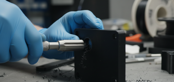
Un trou CAD circulaire numériquement parfait sera-t-il réellement imprimé parfaitement rond en réalité ?
Jamais. L'extrusion thermoplastique entraîne naturellement le plastique fondu légèrement vers l'intérieur lorsque la tête d'outil force un changement de direction circulaire, ce qui donne presque toujours une forme ovale microscopique sous-dimensionnée.
Exécuter un ajustement par pression parfait d'un roulement lourd exige une itération physique impitoyable. Si un ingénieur modélise un trou de dix millimètres pour un roulement en acier, le trou imprimé rétrécit inévitablement à environ neuf virgule six millimètres. Tenter de forcer violemment le roulement métallique lourd dans cette cavité gravement sous-dimensionnée fendra violemment les couches de plastique fragile complètement.
Les vétérans d'usine utilisent une solution mécanique hautement fiable appelée sous-dimensionnement et alésage. Les concepteurs intelligents dessinent délibérément le trou CAD nettement plus petit que nécessaire. Une fois que le plastique physique a complètement refroidi, durci et rétréci, les techniciens utilisent un alésoir mécanique à main très tranchant pour raser lentement l'excès de matériau intérieur, créant un diamètre intérieur parfaitement rond et impeccable.
La transition de collecteurs de fluide complexes vers des SLA (Stéréolithographie) procédés de résine offre une concentricité de trou nettement supérieure par rapport au filament traditionnel qui traîne. Le laser trace le périmètre absolu mathématiquement sans tirer physiquement le matériau fondu. Cependant, une exposition prolongée à la lumière ultraviolette ambiante après durcissement provoque un léger retrait continu de la résine sur plusieurs semaines.
Hub JUCHENG : Dominer les capacités hybrides

Les technologies purement additives peuvent-elles réellement atteindre une précision de quelques microns pour le matériel aérospatial ?
Jamais. Pousser les limites physiques extrêmes exige strictement de prendre le composant imprimé surdimensionné et de fraiser soustractivement les surfaces d'accouplement critiques complètement à plat sur un centre d'usinage rigide.
Exécuter des tolérances de fabrication hybrides hautement avancées sépare les programmes matériels d'élite des projets de bricoleurs amateurs. Les ingénieurs impriment régulièrement des châssis de drones massifs et complexes en polymères légers pour économiser des coûts de matériaux coûteux. Cependant, ils ajoutent délibérément deux millimètres supplémentaires de matériau sacrificiel brut strictement sur les pattes de montage du moteur.
Une fois que le plastique a complètement durci, les techniciens de Jucheng serrent agressivement la pièce en polymère dans un centre d'usinage CNC 5 axes lourd. La fraise en carbure en rotation cisaille violemment l'excès de plastique, laissant une face de montage absolument impeccable et parfaitement plate. Nous livrons une perfection absolue en combinant la géométrie ultime de l'impression avec la précision brutale du fraisage.
Questions fréquemment posées : Réalité dimensionnelle

Est-ce que ralentir la vitesse d'impression par extrusion améliore réellement la précision dimensionnelle ?
Oui. Faire fonctionner le portique mécanique lourd à des vitesses extrêmes induit des vibrations violentes qui fantôment les bords parfaitement droits. Ralentir la machine permet au plastique fondu de refroidir et de se lier plus uniformément, réduisant considérablement le renflement indésirable des coins.
Pourquoi demander des tolérances extrêmement serrées augmente-t-il si agressivement le devis de fabrication ?
Demanding single-digit micron accuracy practically guarantees the part must be transferred to a secondary milling center. This introduces highly expensive fixture setups, specialized tooling, and additional labor hours to perfectly machine the printed faces.
Is massive dimensional shrinkage a problem when scaling into global mass production?
Absolutely. Transitioning a printed design directly into hardened Moulage par injection steel requires massive shrinkage recalculation. Highly crystalline polymers like Le nylon shrink violently inside a pressurized steel mold, forcing tooling engineers to heavily oversize the physical metal cavity.

