


Validating a product’s initial visual concept using additive layer deposition offers incredible creative freedom, but it frequently creates a false sense of manufacturing security. Because printers ignore traditional molding constraints like directional release and melt flow friction, files designed purely for printing will inevitably fail when dropped directly into a metal mold cutting queue. Bridging the gap 3D printing to rapid tooling requires a deliberate CAD redesign mindset to adapt virtual geometries for high-pressure injection molding success.
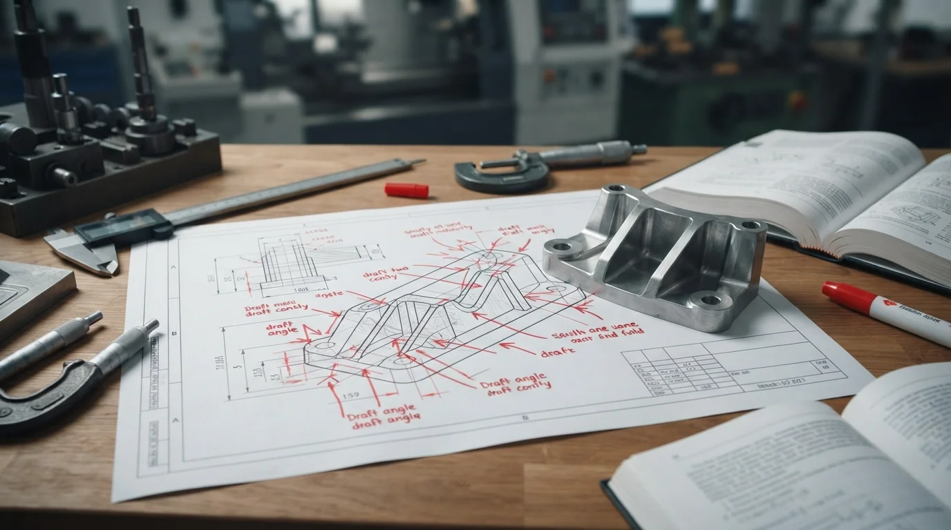
Table des matières
1. The Design Redesign: Preparing Your 3D-Printed CAD for Injection Molding
2. Adding Draft Angles, Uniform Walls, and Removing Undercuts
The Design Redesign: Preparing Your 3D-Printed CAD for Injection Molding
Question: Why must a digital 3D model undergo geometric modifications when transitioning from laboratory additive printing to rapid metal tooling? Additive machines build objects vertically without friction, whereas injection molding requires structural features to separate cleanly from metal mold halves along a designated parting line.
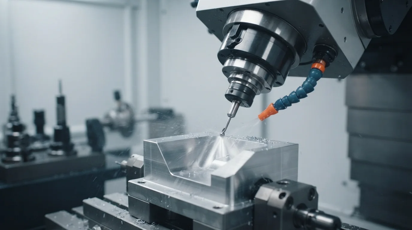
When shifting production gears from a conceptual 3D print to an injection-molded bridge tool, engineers must restructure internal rib networks, eliminate sharp right-angle wall junctions, and resolve complex side-action requirements. Utilizing a specialized Service de prototypage or agile Service d'usinage CNC helps bridge this digital evolution safely.
Contrasting design criteria across additive versus molded workflows involves tracking specific preparation metrics:
| Geometric Feature | 3D Printing Design Freedom | Rapid Injection Molding Requirement |
|---|---|---|
| Vertical Wall Angles | True 90-degree vertical walls are standard | Requires 0.5 to 2 degrees of draft for clean ejection |
| Internal Undercuts | Accommodated via support structures | Requires mechanical side-actions or slide cores |
| Wall Thickness Transitions | Arbitrary mass pockets allowed | Must maintain uniform walls to prevent sink marks |
Adding Draft Angles, Uniform Walls, and Removing Undercuts
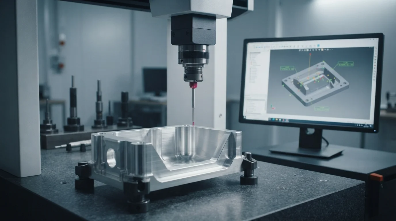
Question: What specific geometric adjustments prevent molded parts from sticking or binding inside a rapid aluminum mold core? Incorporating subtle taper angles on vertical walls and eliminating hidden undercuts ensures parts release smoothly without surface scratching.
If vertical walls lack proper draft, ejector pins will punch straight through the cooling polymer during extraction. Similarly, hidden snap-lips or side pockets that function effortlessly in flexible printed resins will lock rigid metal mold halves together unless redesigned with sliding lifters or collapsible cores. Utilizing an agile Service de moulage par injection ensures these structural elements are optimized before tool cutting begins.
Optimizing CAD data for bridge tooling and eliminating release friction involves monitoring key engineering guidelines:
- Applying minimum draft angles—Adding at least one degree of taper to vertical surfaces to facilitate smooth mold opening
- Coring out thick bosses—Hollowing out heavy screw connections to prevent localized volumetric shrinkage and sink marks
- Eliminating acute corners—Blending sharp internal angles with generous radii to enhance resin flow and structural strength
Free DFM Check: Let Jucheng Bridge the Gap for You

Jucheng Precision soutient les développeurs de matériel en fournissant des analyses DFM gratuites 24h/24 reviews that evaluate draft angles, wall uniformity, and undercut risks instantly. Operating with 150+ advanced CNC machines alongside 35+ specialized injection molding workstations, our ISO 9001 certified facilities ensure seamless execution across every transition phase.
Key operational advantages of our engineering optimization framework include:
- Expert DFM CAD evaluation—Identifying print-to-mold geometric conflicts before cutting metal
- High-speed rapid tooling—Cutting durable aluminum and steel inserts within days to support pilot rollouts
- Aucune contrainte de quantité minimale de commande—Aucune politique de MOQ ne permet un alignement exact des stocks avec des séries de production pilotes personnalisées
Ready to transition your prototypes into production? Upload Your CAD Files Today for Expert Engineering Review at Jucheng Precision.
Foire aux questions (FAQ)

Why must 3D printed CAD models be modified before rapid tooling production?
Additive printers build objects vertically without friction, whereas injection molding requires structural draft angles, uniform wall distributions, and parting line alignment to separate from metal mold halves cleanly.
What geometric features cause the most trouble when moving from prints to molds?
True 90-degree vertical walls, sudden wall thickness transitions, and hidden internal undercuts cause the most friction during mold release unless redesigned with draft and side-actions.
How does Jucheng Precision help bridge the gap from prototypes to production?
Jucheng Precision provides 24-hour free DFM reviews, expert CAD optimization guidance, and rapid injection molding services to ensure a seamless transition from additive labs to metal bridge tools.

