


Why axis access matters
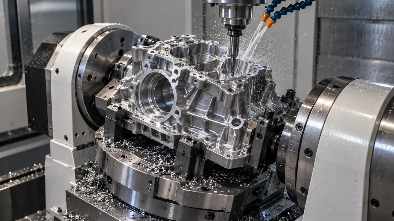
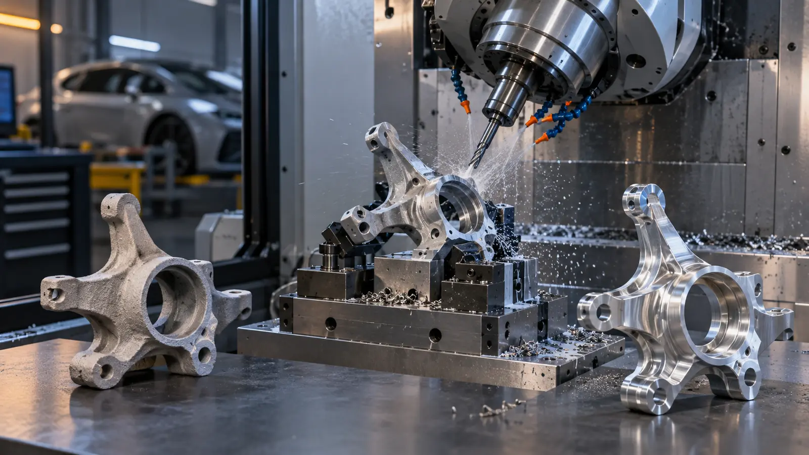
In conventional milling, the workpiece is often repositioned so the tool can reach another face. Each repositioning adds workholding decisions and can change the relationship between the part and its original datum. Five-axis machining changes the access strategy by tilting the tool or workpiece, allowing more features to be reached from a connected setup.
This does not mean every operation runs simultaneously. Many projects use indexed five-axis positioning for selected faces and use three-axis toolpaths for the rest. The right mix depends on the part’s critical surfaces and the evidence required by the vehicle program.
For an automotive prototype, automotive rapid prototyping benefits when complex geometry can be produced without turning a design review into a workholding experiment.
Geometry that earns five-axis attention
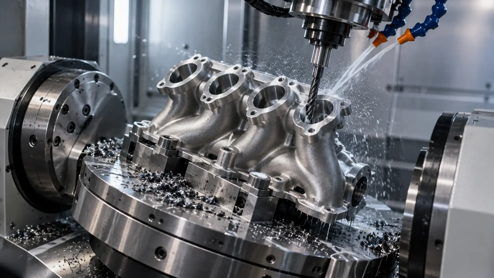
Typical candidates include impeller-like forms, curved housings, sculpted brackets, inclined bores, deep cavities, and components with multiple intersecting surfaces. Five-axis access can also help when a cutter must remain normal to a surface to improve finish or avoid excessive tool extension.
| Geometry signal | Potential benefit | Question to confirm |
|---|---|---|
| Features on many faces | Less manual repositioning | Which faces share critical datums? |
| Deep or narrow pockets | Shorter, more rigid tool orientation | Can the tool reach without collision? |
| Compound curves | More consistent contact angle | Is surface quality functional or cosmetic? |
| Angled holes | Better alignment to the design axis | How will the hole be inspected? |
A complex model alone is not a reason to specify five-axis machining. A part with broad flat faces and simple perpendicular holes may be cheaper and easier to inspect with a three-axis process.
Fewer setups, clearer datums
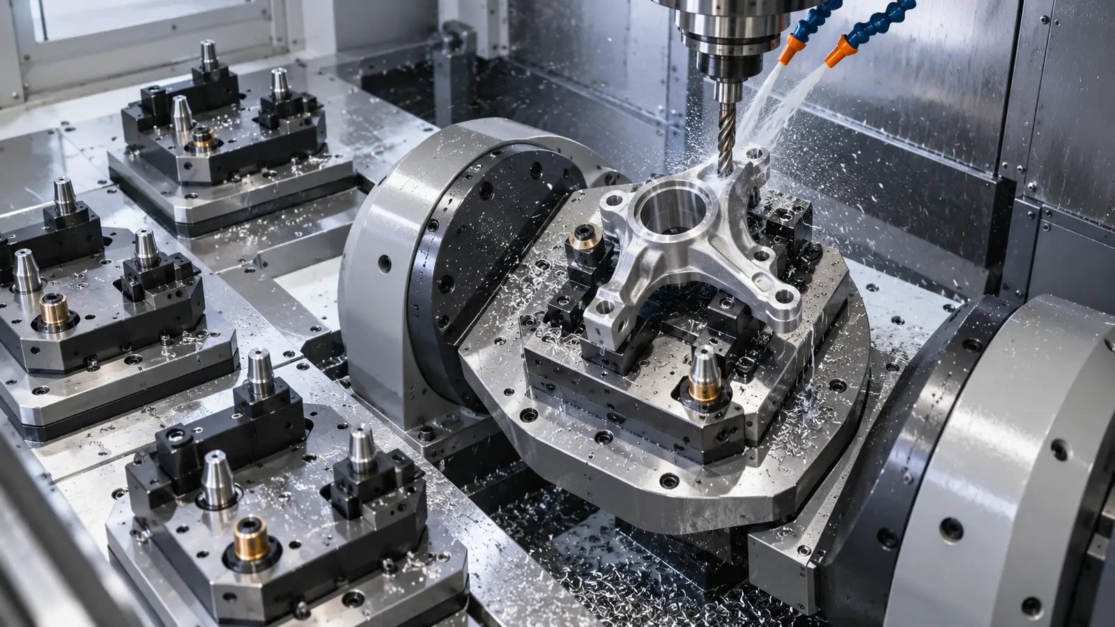
Setup reduction is most useful when it protects the relationships that make the part assemble. A bracket with mounting holes on several planes may be more reliable when those planes are machined from one controlled reference. A housing with a bore, sealing land, and angled connector face may benefit from a strategy that preserves their relative position.
However, fewer setups do not remove the need for workholding design. The fixture must still provide access, support thin walls, control distortion, and leave room for probing or inspection. Engineers should review clamping forces before assuming that a single setup is automatically more accurate.
Material and cutter behavior
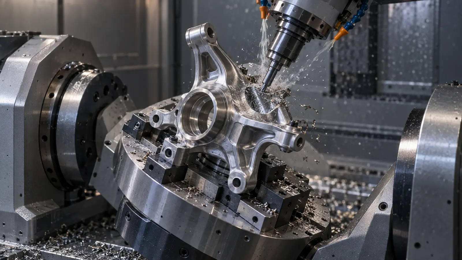
Aluminum is commonly considered for lightweight prototype parts and tooling because it cuts efficiently and can accept anodizing or other finishes. Stainless steel and alloy steel demand more attention to heat, work hardening, tool wear, and chip evacuation. Engineering plastics may require different support and clamping decisions because deflection can dominate the tolerance result.
Le CNC machining service should be selected with the material, tool access, quantity, and critical features in view. The same toolpath is not equally suitable for every alloy or polymer.
Inspection of multi-face parts
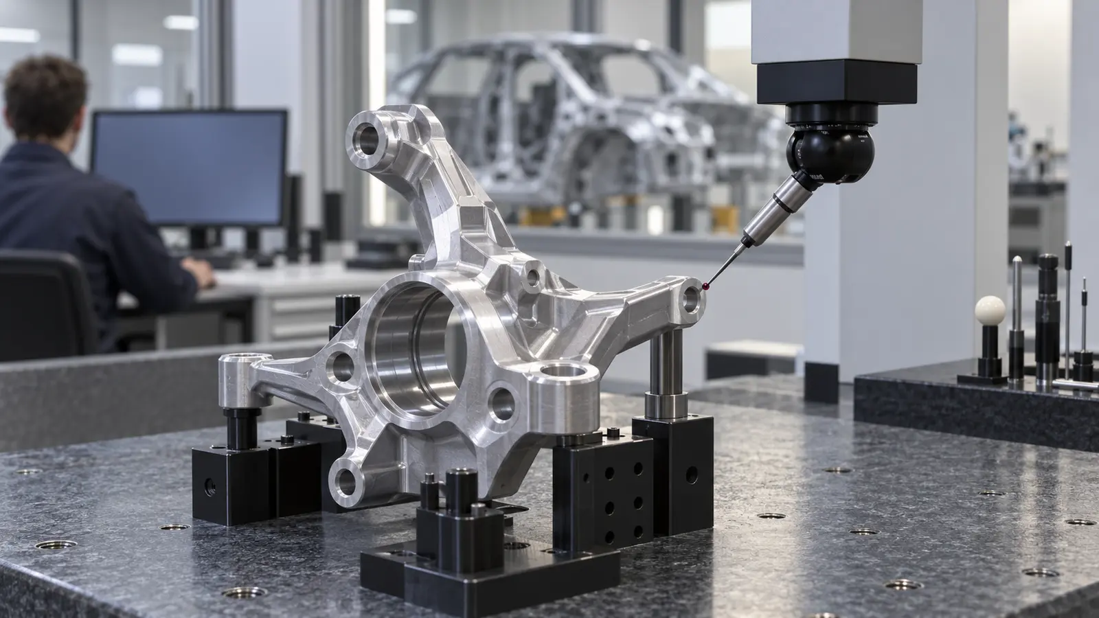
Inspection should preserve the design intent across faces. A feature may be within size tolerance but still fail because its position is wrong relative to the primary datum. The drawing should identify the reference system, geometric controls, and surfaces that establish assembly.
Depending on the requirement, verification may involve a coordinate measuring machine, optical measurement, height measurement, gauges, or a combination of methods. The inspection plan should be agreed before production so that inaccessible or treated surfaces are not discovered too late.
A practical process decision
- Mark every functional face, bore, pocket, and interface.
- Group features by the datum that controls them.
- Identify where a second setup could introduce meaningful error.
- Compare five-axis, three-axis, turning, casting, and molding routes.
- Choose the simplest route that delivers the required evidence.
Five-axis machining is often strongest when it protects a difficult relationship, not when it merely makes the machine sound more advanced. Quantity, revision frequency, finish, and inspection expectations should remain part of the decision.
Frequently Asked Questions
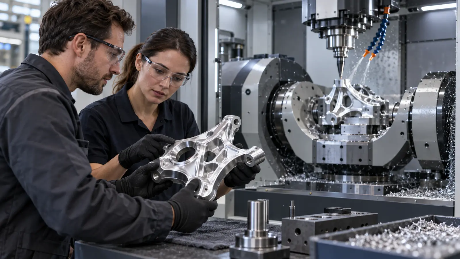
What automotive parts benefit from five-axis CNC machining?
Complex housings, curved brackets, inclined components, tooling parts, and prototypes with important features on multiple faces are common candidates.
Is five-axis machining more accurate than three-axis machining?
Not automatically. Its advantage is access and setup strategy. When fewer setups protect critical datums, it may improve consistency; the actual result still depends on machine, tooling, workholding, programming, and inspection.
Can five-axis machining support automotive prototypes?
Yes. It can produce complex metal or plastic prototypes for fit, function, and design validation when the geometry cannot be efficiently reached with simpler setups.
Does five-axis machining eliminate the need for fixtures?
No. A fixture is still needed to locate and support the workpiece. Five-axis movement changes tool access, but it does not remove workholding or distortion considerations.
Let the geometry justify the axis count
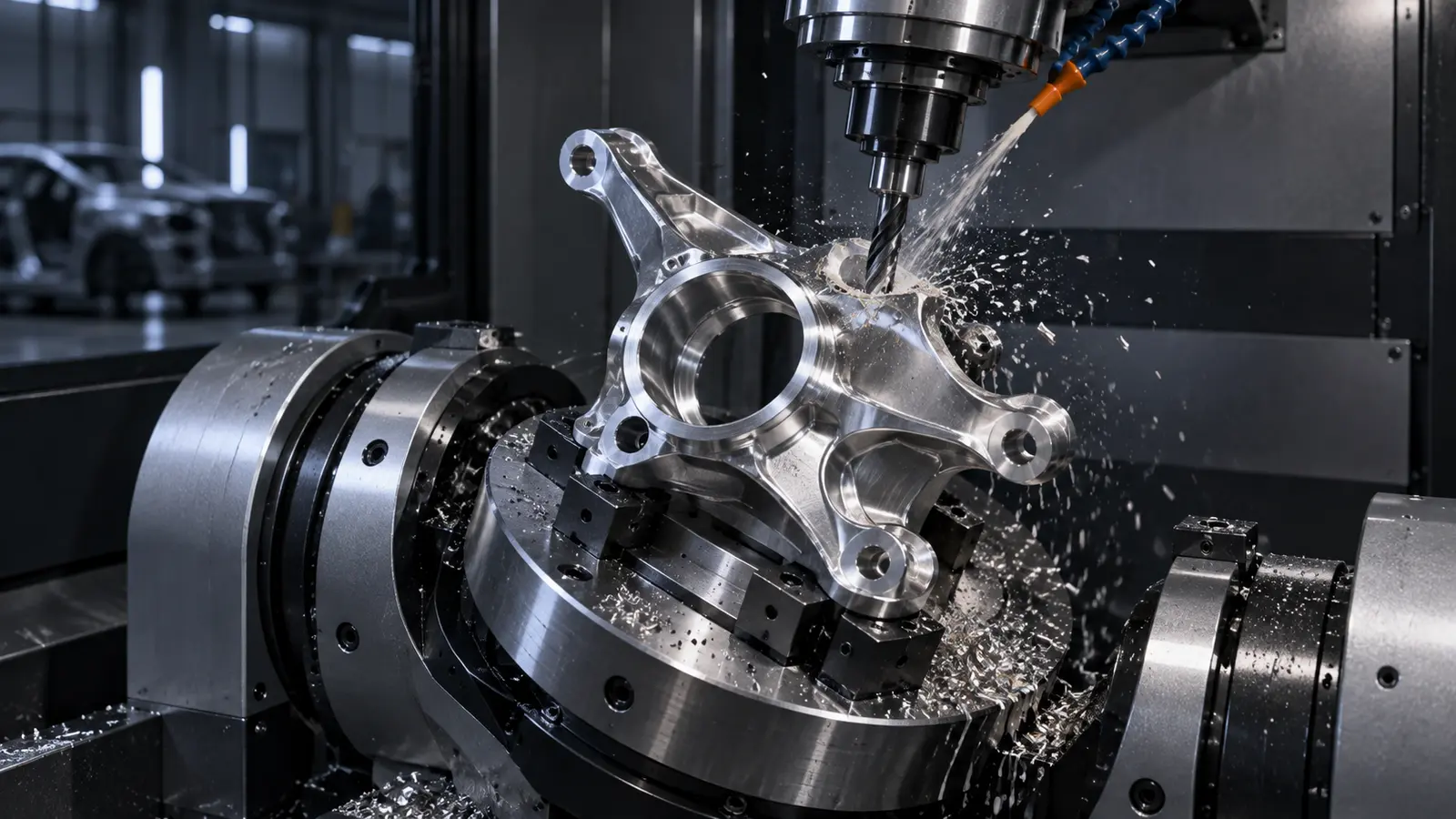
The best automotive 5 axis CNC machining projects begin with a clear relationship between geometry and evidence. If the part needs complex access, controlled datums, or a surface that cannot be reached efficiently after repositioning, five-axis machining can reduce development risk. If it does not, a simpler process may provide the same result with less programming and inspection effort.

