


A control-surface hinge is a small component with a demanding job: preserve the intended pivot relationship while transferring load through a compact attachment. For manufacturing, the challenge is not simply producing a pin hole. Bore alignment, lug geometry, edge distance, surface condition, and inspection access all contribute to whether the hinge behaves as designed.
A useful prototype drawing explains which features locate the part, how the hinge mates with its neighboring structure, and what condition governs acceptance. Without those details, a supplier can make a visually convincing component while missing the functional relationship that the assembly depends on.
Describe the motion and its limits
Start with the assembly movement rather than the isolated hinge outline. Identify the rotation axis, permitted travel, adjacent part envelopes, and any hard stops or clearance limits. If the hinge has multiple leaves or brackets, show their installed orientation and the direction in which the pin is inserted or removed.
Clarify whether the hinge is intended to rotate freely, operate with controlled friction, or function as a fixed alignment joint during a specific state. These are different requirements and may lead to different clearances, bushings, finishes, or assembly details. The manufacturer should not infer friction or wear criteria from a nominal pin diameter.
Interference review should include the full motion envelope and manufacturing variation. A static CAD fit at one angle can miss contact near the travel limit. If the surrounding control surface or support structure is not final, record the reference model version and the assumptions used for the prototype.
Make the pivot axis the controlling reference
For a multi-lug hinge, the relationship among bores matters more than each bore’s location measured independently from an arbitrary edge. Define a datum strategy that controls the axis, such as a common centerline, coaxiality requirement, or a functional fixture condition. The exact tolerance should come from design analysis and assembly needs rather than a generic “precision” label.
Specify bore size, form, and finish where they affect pin fit or bearing behavior. If a bushing or bearing is installed later, identify whether the finished bore is inspected before or after installation. State how the hinge is supported during measurement; clamping thin ears can change the apparent alignment.
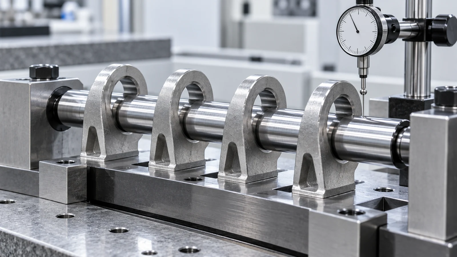
When mating leaves are supplied separately, provide the intended stack order and gap. A gauge or assembly fixture may be more useful than measuring every feature in isolation, particularly for prototype validation. The goal is to verify the assembled pivot function without obscuring the individual part’s drawing requirements.
Design lugs for load transfer and tool access
Lug thickness, root radius, edge distance, and surrounding web geometry affect both load transfer and manufacturability. The responsible design authority should define structural limits. Manufacturing review can then identify whether tools can reach the root, whether the feature can be finished, and whether inspection can access the required surfaces.
Small internal radii may require specialized tooling or extra operations; deep narrow slots can be difficult to machine and inspect. Conversely, increasing a radius or changing a web may alter stress behavior. Treat such changes as design decisions requiring approval, not casual shop-floor edits.
Check pin insertion clearance, retaining hardware, and wrench access in the assembly. A robust lug that cannot be assembled without damaging a finish is not a successful interface. Include the retainer and adjacent bracket in the model when they influence tool approach or motion.
Sequence the manufacturing operations
Operation order influences axis alignment. A typical planning discussion may compare machining both lugs from a common setup, machining one side and using a controlled re-fixture, or producing a near-net shape followed by finish machining. The appropriate route depends on material, geometry, quantity, stock condition, and the specified tolerance.
Thin ears and asymmetric sections can move as material is removed. Leave support stock where useful, balance roughing, and consider a stress-relief or intermediate inspection step only when the material specification and process plan justify it. Do not promise a particular distortion result without evidence from the actual part and setup.
Prototype quantities can favor flexible fixtures, but the datum logic should still resemble the intended assembly. An improvised setup that produces one acceptable sample may not be repeatable. The relevant aerospace manufacturing process should be selected with the inspection plan in mind, not only cycle time.
Keep material and surface requirements connected
Material grade, temper or condition, heat treatment, and surface treatment can affect machinability, strength, wear, corrosion behavior, and final dimensions. Use the exact controlled specification, including revision and condition, rather than relying on a broad label such as “aircraft aluminum.” Material certificates and process records should match the purchase order and project requirement.
Where a coating or surface treatment changes dimensions, account for it at the pin bore, contact faces, and assembly fits. Masking, post-treatment sizing, or an agreed allowance may be needed, but the drawing and process owner must define the accepted approach. A finish selected only for appearance can change friction or wear at a moving interface.
For general context on aerospace materials, compare material families against the intended function and available specifications. Do not substitute a material based only on nominal strength or availability.
Inspect alignment with a functional setup
Inspect the datum features first, then evaluate bore diameter, position, form, and axis relationship. A common mandrel can reveal whether the bores accept a straight pin through the intended stack, but it does not replace dimensional records if the drawing requires them. State whether the measurement is free-state or fixture-held.
Use inspection equipment suited to the geometry and tolerance. A coordinate measuring machine can capture relationships; dedicated gauges can provide a practical functional check. Identify the method, calibration expectations, and acceptance record required by the buyer. Avoid claiming compliance to an unspecified aerospace standard.

After dimensional inspection, assemble representative mating parts and check pivot motion, travel limits, retention, and clearance. Record the configuration and hardware used. This separates “the part measures correctly” from “the assembly behaves as intended,” two checks that may answer different questions.
What the drawing package should resolve
- Assembly orientation, pivot axis, travel limits, and adjacent envelopes.
- Datum scheme and bore relationship across all lugs or leaves.
- Pin, bushing, retainer, and hardware ownership.
- Material specification, condition, finish, and masked interfaces.
- Critical edge distances, root radii, and approved design-change process.
- Inspection condition, functional gauge or fixture, and required records.
- Prototype purpose, quantity, revision, and any deviations from production intent.
Resolving these items before quotation reduces ambiguity around setups and acceptance. If a requirement is not yet defined, call it out as an open design item rather than embedding an assumption in the manufacturing plan.
Frequently asked questions
Is bore diameter enough to control hinge performance?
No. Bore alignment across the hinge stack, pin fit, support condition, and mating geometry can all affect pivot behavior.
Can a supplier change a lug radius to improve machining?
Only with approval from the design authority when the change affects structural geometry. A manufacturability suggestion is not authorization to alter a controlled design.
Does a functional pin check replace dimensional inspection?
Not unless the drawing or quality plan defines it as the acceptance method. Functional checks and dimensional records often provide complementary evidence.
For the wider component context, the aviation and aerospace prototyping page connects this hinge topic to the broader aircraft development scope. When the pivot axis, load-bearing geometry, finish, and inspection setup are defined together, hinge manufacturing can focus on the relationship that governs the assembly instead of chasing isolated dimensions.

