


Aircraft hydraulic fittings connect tubes, hoses, components and manifolds while preserving the intended fluid path and seal. A fitting selection is not complete when a thread size appears to match: the connection standard, sealing surface, tube or hose interface, installation access and system documentation must agree. SAE’s current ARP994C recommended practice for aerospace hydraulic tubing installations covers design and selection of tube, hose and fitting systems, reflecting that these parts belong to a controlled installation rather than a standalone catalog choice.
For manufacturers, the same interface logic affects how a custom block, adapter or fitting is modeled, machined, inspected and documented. This article explains the decision points without substituting for approved aircraft maintenance instructions or the program’s engineering authority.
Contents
- Start at the connection, not the catalog label
- Fitting families solve different interface problems
- Threads retain; the seal surface does the sealing
- Routing and wrench access are part of the design
- Manufacturing details that protect the interface
- Inspection and records close the loop
- Frequently asked questions
Start at the connection, not the catalog label
A drawing may list a thread callout, but a complete connection definition needs to say how the fitting seals and what it mates with. A tapered thread, an O-ring boss, a flared tube connection and a face-seal connection do not share the same sealing logic. Similar diameters or nominal sizes do not make two systems interchangeable.
Build an interface table for every connection. Record the fitting part or standard, mating line type and size, thread designation, seal feature, orientation, material, installation envelope and any pressure or temperature requirement supplied by the system design. When a fitting attaches to a manifold, include the port callout and sealing face from the block drawing.
Where a legacy assembly is being reproduced, verify the actual controlled drawing and revision rather than inferring requirements from a removed part. A damaged or corroded fitting may not represent the original nominal geometry. The FAA’s AC 65-9A airframe and powerplant mechanics handbook discusses aircraft line and hose installation practices, including care needed during assembly; approved maintenance data remains controlling.
Document uncertainty explicitly. If the connected line or seal family is unknown, mark it as an engineering question. Guessing a fitting can create a leak path or force an improvised adapter into a system that was not designed for it.
Fitting families solve different interface problems
Common aircraft fluid connections include rigid-tube fittings, hose-end fittings, adapters and fittings that attach directly to a component port. The relevant distinction is how each connects and seals, not simply the angle or shape of the body.
| Connection family | Typical interface logic | Design review focus |
|---|---|---|
| Flared tube connection | Tube end forms a sealing surface against a mating seat | Flare geometry, tube preparation, alignment and tightening method |
| Flareless or compression-style connection | A sleeve or ferrule grips and seals against a specified tube | Tube material, wall, preparation and approved assembly procedure |
| Hose-end fitting | Connects a flexible hose to a port or another assembly | Hose compatibility, end configuration, bend radius and torsion |
| Port adapter | Bridges a component port to a line connection | Thread family, seal method, orientation and added joint count |
This table is an orientation aid, not an installation instruction. Each aircraft system may prescribe specific families and parts. Never combine connection types because their nominal dimensions appear close. Fittings, tube material and assembly method must be selected as a compatible system.
Adapters deserve special scrutiny. They can solve a packaging interface, but every added joint creates another point to identify, assemble and inspect. If an adapter is required, confirm that its length, clocking, tool access and line support fit the available envelope.
Threads retain; the seal surface does the sealing
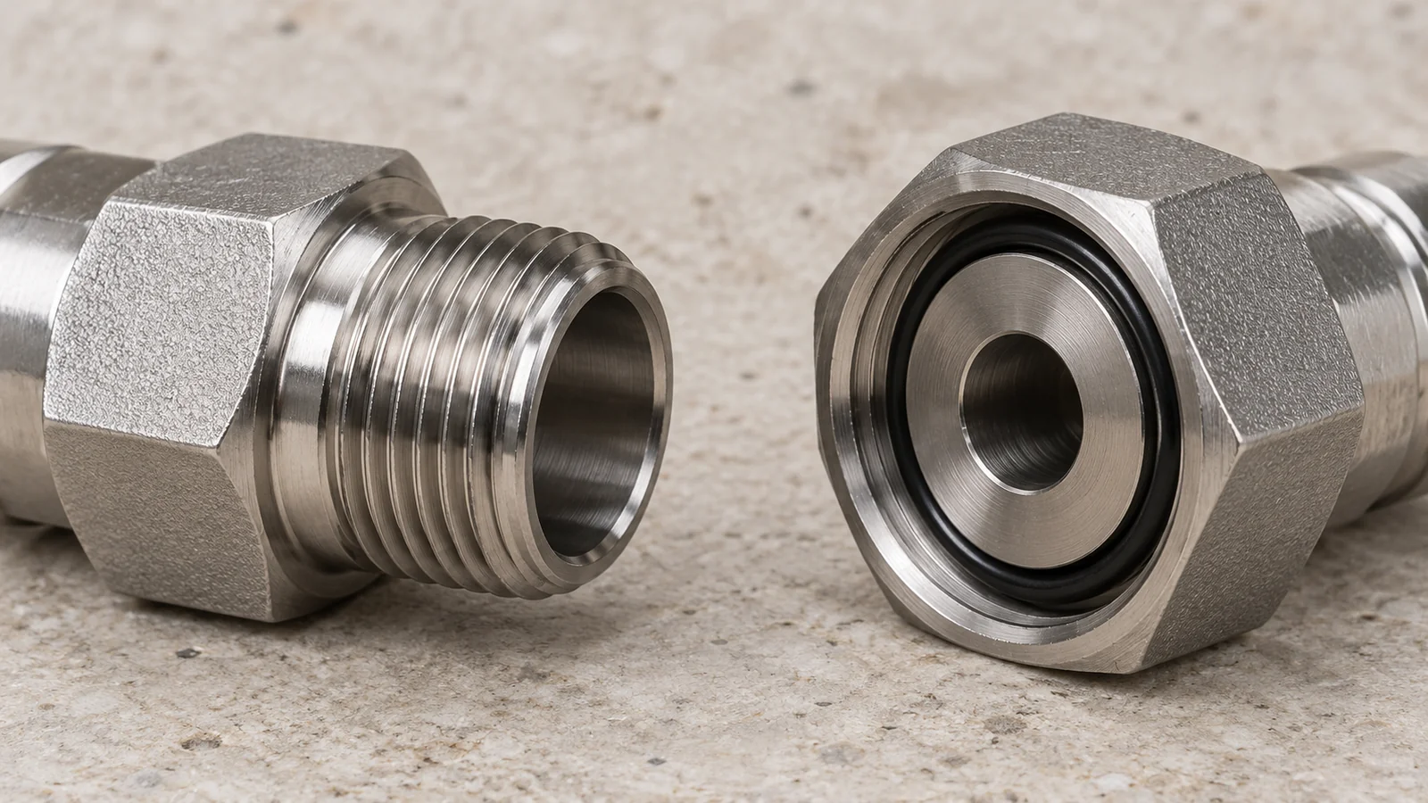
One recurring design error is to assume that every threaded connection seals on the threads. Some designs use thread engagement to retain a fitting while a flare, O-ring, cone or face provides the sealing contact. The drawing should make the active seal feature clear so machinists and assemblers do not treat the thread as the only functional surface.
Seal performance depends on geometry and condition at the mating interface. Burrs, scratches, contamination, damaged coating or a poor transition at the port mouth can compromise contact. If an O-ring is used, groove dimensions, compression, gland fill and surface condition must follow the approved design. Avoid copying an O-ring groove from another part without checking the specific seal and environment.
Do not use a generic torque or pressure value in place of the approved assembly specification. Correct tightening depends on the connection family, size, lubrication state and assembly procedure. The technical article can explain the design logic, but it should direct installation teams to the controlling maintenance and engineering documents.
For custom machined ports, specify the sealing face, thread, lead-in and datum relationship together. This lets manufacturing plan the operation sequence and inspection rather than treating a port as a simple drilled hole.
Routing and wrench access are part of the design
Fitting selection changes tube routing. A straight fitting, elbow or swivel may solve a packaging conflict, but orientation can also introduce bending, torsion or interference. Review the connection in the installed assembly with adjacent structure, wiring, moving equipment and removal paths visible.
Keep the fitting body and tube support in the model. Confirm that a wrench or prescribed tool can reach the connection without contacting nearby parts. Ensure that a tube can be installed without forcing its alignment into the fitting. Flexible hose should not be twisted to achieve clocking, and line support should follow the approved design.

Allow room for inspection and replacement. A connection hidden behind a panel may be difficult to check for leakage or service. An assembly that requires removing several unrelated components to reach a fitting can raise maintenance burden and increase the chance of disturbing neighboring lines.
At the manifold, port spacing should be checked with real fitting envelopes rather than simplified cylinders alone. Include wrench swing, connector length and line bend in the layout. For a new prototype, these clearance checks can reveal whether a fitting family or port orientation needs to change before detail machining.
Manufacturing details that protect the interface
Manufacture begins with a controlled definition of thread form, thread class, sealing seat, surface finish, concentricity or position, and any required chamfer. The feature list should distinguish critical sealing surfaces from nonfunctional external edges. A callout that only states nominal thread size may leave the sealing geometry underspecified.
For machined parts, tool access and setup affect the relationship between the port axis and the sealing face. If a port intersects an internal passage, deburring and cleaning must be planned. Thread and seat operations should be sequenced to avoid damaging a finished seal surface during later handling or coating.
Material and treatment choices also affect the interface. A surface treatment may change dimensions or surface behavior; a dissimilar-metal connection may require corrosion review. The exact alloy, finish and material condition must come from the approved design. Our aerospace materials guide offers general context for evaluating those tradeoffs.
When a custom adapter or ported body requires turned and milled features, review setup access and drawing datums with our aerospace CNC machining overview. The supplier should receive the mating interface definition, not just a 3D silhouette.
Inspection and records close the loop
Inspection should focus on the characteristics that make the connection functional: thread form, seat or groove geometry, port location, sealing-surface condition and any required material or finish evidence. Measurement methods should be appropriate to the geometry and specified tolerance. A visual check alone may not be enough for a critical thread or sealing surface.
Keep records tied to the part number and revision. Material certificates, process records, inspection results and any test evidence should identify the configuration they support. If the part is a prototype, label the intended evaluation scope and any requirements not yet demonstrated.
Assembly instructions should identify the approved fitting and mating line, required preparation, sequence and inspection points. FAA handbook material can provide general education, but the aircraft’s approved maintenance data and engineering documents govern actual installation. This distinction prevents a general blog explanation from being mistaken for an authorized repair procedure.
A useful final review asks whether a buyer, machinist and installer would all identify the same fitting family, seal surface, orientation and proof of conformity from the released package. If not, clarify the interface before purchasing or cutting material.
Frequently asked questions
Can two fittings with the same thread size be interchanged?
Not necessarily. They may use different thread forms, sealing surfaces, tube interfaces, materials or approved applications. Confirm the controlled part and interface definition rather than relying on nominal size alone.
Does the thread always provide the hydraulic seal?
No. Some connections seal at a flare, cone, O-ring or face while the thread retains the fitting. The drawing should identify the actual sealing feature and mating geometry.
What information should be sent for a custom fitting or adapter review?
Provide the mating port and line standards, controlled drawing, material and condition, seal details, orientation, envelope, operating requirements from the system owner, quantity and inspection expectations. Mark any unapproved assumptions.

