


A rocket engine injector plate contains a pattern of passages and openings whose geometry is tied to a controlled propulsion design. The manufacturing challenge is to preserve that geometry, its relationship to the plate’s sealing and mounting faces, and the cleanliness required by the system. Rocket engine injector plate machining is therefore not a matter of simply drilling a specified pattern; it requires a controlled model, a defined datum scheme, and an acceptance plan from the propulsion authority.
This article addresses manufacturing planning and drawing readiness, not injector design or performance. Orifice size, pattern, flow characteristics, materials, joining, and test criteria are determined by the engine design team. A machine shop should not infer those values or claim that machining conformance alone demonstrates engine performance.
Contents
- Freeze the controlled geometry first
- Choose datums that preserve the flow pattern
- Plan the sequence for intersecting passages
- Coordinate material condition and joining
- Treat cleanliness as a manufacturing requirement
- Match inspection to the feature
- Keep manufacturing acceptance separate from propulsion testing
Freeze the controlled geometry first
Before quotation, confirm the released drawing, 3D model, revision, and engineering-change status. Identify the controlled passage geometry, sealing faces, mounting features, and any interfaces to manifolds or engine structure. If a hole pattern or passage detail is proprietary or controlled by a propulsion authority, the supplier should receive the approved data through the program’s normal information-control process.
Ask which dimensions are functionally critical and which are general. A dense pattern can make inspection difficult, and not every visible edge will have the same effect on the assembly. The design authority should identify the acceptance characteristics, measurement methods, and any prohibited deviations.
Keep the design baseline synchronized across the drawing, model, and manufacturing instructions. If a passage is moved or a sealing face changes after toolpath preparation, the affected setup and inspection plan must be revised. Avoid machining to a stale STEP file when the controlled drawing has a newer revision.
Choose datums that preserve the flow pattern
A datum scheme should connect the injector pattern to the sealing face and mounting interface. Define how the plate is located and oriented during machining, and how the same references will be used in inspection. If the pattern is controlled relative to a centerline, bolt pattern, or chamber interface, state that relationship explicitly.
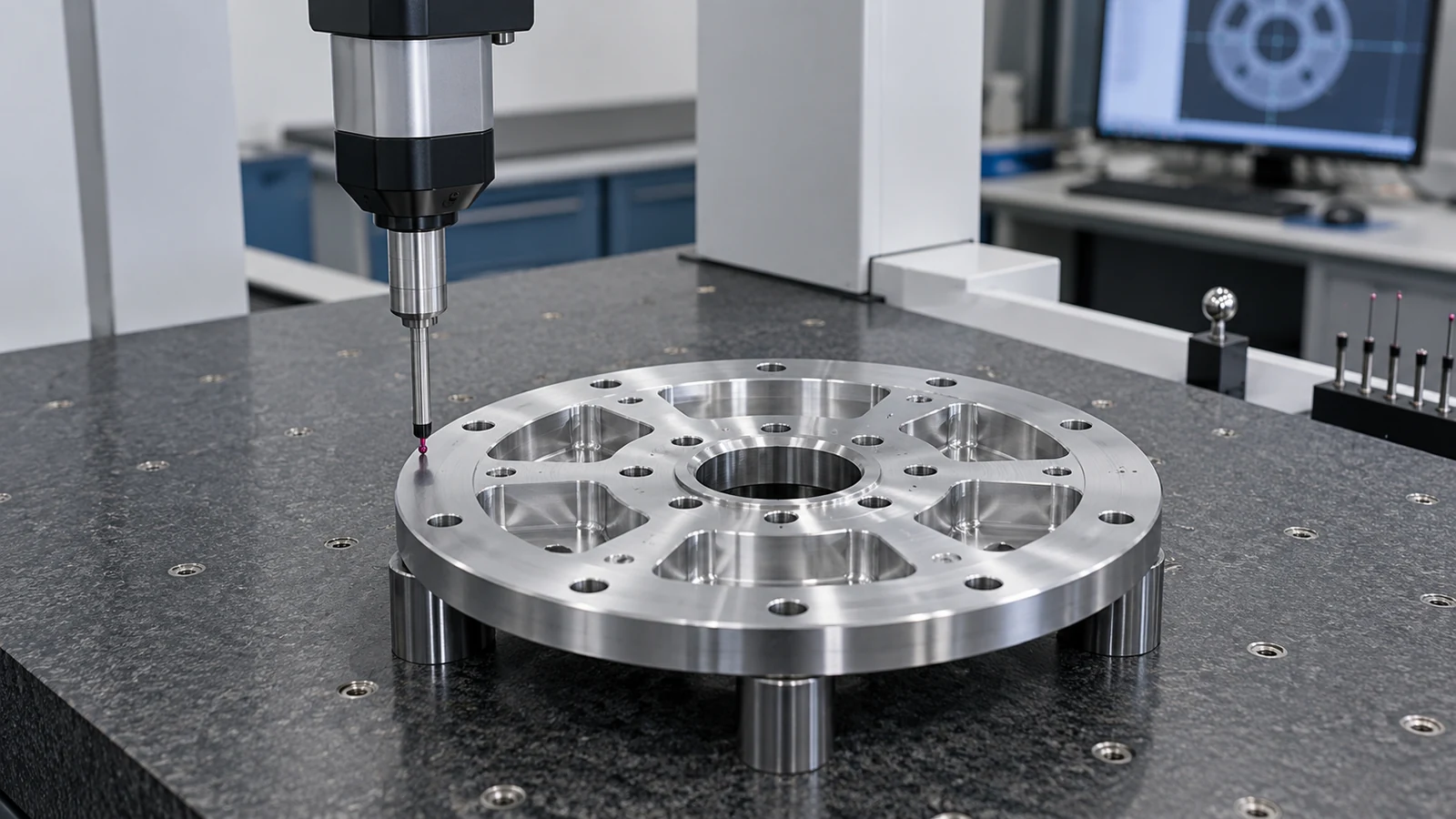
Consider the full tolerance stack from the plate to the mating component. A hole can be within its local position tolerance while the assembled pattern is shifted relative to the chamber or manifold. Coordinate the plate’s datums with the adjoining part so that inspection verifies the intended interface.
For a large or thin plate, support conditions can affect flatness. Define whether the sealing face is measured free-state or under a specified restraint. If a fixture is used, it should reproduce the functional setup without hiding distortion or forcing the plate into compliance.
Plan the sequence for intersecting passages
Injector plates may contain through-holes, angled features, counterbores, and intersecting passages. Their sequence affects burr formation, tool access, chip removal, and the final condition at internal intersections. The design authority should specify which edges require controlled breaks and which internal features must remain free of burrs or obstruction.
Manufacturing planning should identify tool approach, workholding, indexing, and how the plate is re-referenced between setups. Where passages intersect, determine how chips and residues are removed and how the internal geometry can be inspected. A process that creates an inaccessible burr or trapped chip is not acceptable merely because the external dimensions pass.
In some designs, drilling, milling, EDM, or other processes may be considered for different features. The selection depends on material, geometry, surface requirements, and the approved manufacturing plan. Do not assume that a process name establishes passage quality; define the required result and verification evidence.
Coordinate material condition and joining
Material and condition should come from the released propulsion specification, including alloy or grade, temper or heat treatment, traceability, and any permitted substitutions. The required choice can depend on the engine’s temperature, pressure, fluid compatibility, structural loads, and joining method. No generic material recommendation is suitable for every injector plate.
If the plate is bonded, brazed, welded, or joined to another component, the sequence matters. Joining can distort sealing faces or passage alignment, and post-join machining may be part of the controlled route. The joining procedure, filler, inspection, and acceptance must be specified by the responsible engineering authority.
Surface finish and coatings also affect sealing, contact, cleanliness, and compatibility. Identify which faces are critical, what treatment is allowed, and whether masking is required. The CNC machining capability can be reviewed for the defined geometry, material, and inspection package; the propulsion specification remains controlling.
Treat cleanliness as a manufacturing requirement
Cleanliness should be designed into the process route, not added as a last-minute wash. Specify the allowed residues, cleaning method, handling controls, packaging, and inspection records. Internal passages can retain chips, coolant, abrasive media, or cleaning residues that are not visible from the exterior.
Plan how each passage is flushed, dried, and inspected. The method must be compatible with the material and propulsion system, and acceptance criteria should be defined by the program. A visual examination may detect obvious contamination but cannot by itself prove the absence of all particles or residues.
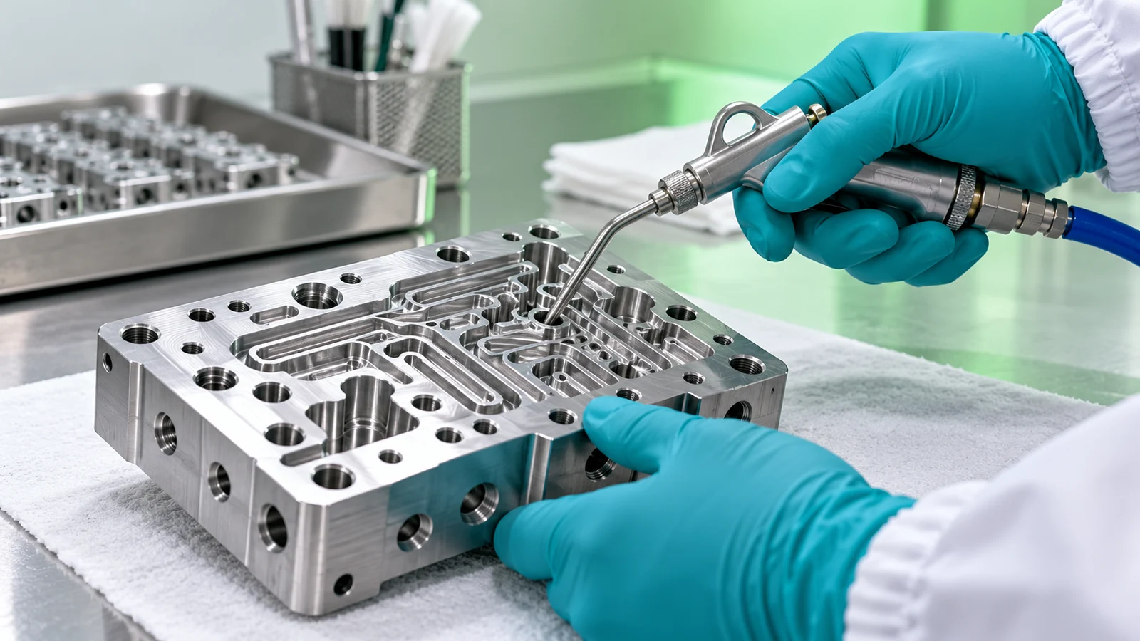
Protect the plate between operations. Cover open passages during handling, avoid unapproved marking near critical surfaces, and control the storage environment if required. Traceability should link the finished component to its material and process records.
Match inspection to the feature
Inspection methods should reflect feature geometry and required uncertainty. Coordinate measurement can verify external datums and accessible positions. Pin gauges or optical systems may be appropriate for some openings. Internal passage inspection may require borescope, flow, or other program-approved methods. Each method has limits that should be understood and recorded.
Use first-article inspection to confirm the planned setup, process sequence, and measurement approach before repeating a batch. Record the revision, material identification, finish state, equipment, and actual results for designated characteristics. If a feature cannot be measured directly, obtain design-authority approval for an alternate method rather than silently substituting a visual judgment.
Keep the inspection record tied to the final state. If joining, coating, or post-process machining changes a dimension or passage, the acceptance plan should identify when the characteristic is checked and what evidence is retained.
Keep manufacturing acceptance separate from propulsion testing
Dimensional and cleanliness acceptance establish conformance to the component definition. They do not establish combustion stability, flow distribution, thrust, or engine qualification. Those are system-level questions answered under the program’s propulsion test plan.
A useful delivery package identifies the drawing revision, material traceability, process records, inspection results, cleaning and packaging records, and approved deviations. The program determines which documents are required and how the part is released for integration.
At low quantities, a prototype build can support process and interface learning where the program permits it. Keep prototype status explicit, and do not use an engineering sample as a substitute for an accepted flight component.
The plate is only as reliable as its controlled interface
Reliable rocket engine injector plate machining depends on a stable data baseline, datums tied to the chamber interface, a deliberate passage sequence, approved materials and joining, controlled cleanliness, and inspection matched to each feature. When those controls are defined before release, the supplier can manufacture and document the component without being asked to infer propulsion intent.

