


A medical suction tube connector is a small interface with a surprisingly broad job: it joins a specified tube to another device component while preserving the geometry and handling characteristics required by the product design. Its taper, barb, socket, shoulder, bore, and surrounding grip features can all affect fit. Because the connector may be molded or machined as part of a larger assembly, the manufacturing plan should begin with the mating system and the drawing, not with a generic connector shape. The term medical suction tube connector manufacturing describes this drawing-led part and process scope; it does not replace the program’s approved design requirements.
This article is for engineers and buyers developing custom connector components or prototypes. It explains how to define the interface, choose a route, manage material and molding considerations, and plan inspection. It does not establish clinical suitability, flow performance, sterilization compatibility, or regulatory compliance. The finished-device manufacturer must define and validate those requirements for the specific device and intended use.
Contents
- Define the complete connection stack
- Separate retention from sealing geometry
- Specify the polymer and its condition precisely
- Select molding or machining for the development question
- Review mold details around the bore and port
- Make fit and inspection criteria repeatable
- What information belongs in the supplier package?
- Frequently asked questions
Define the complete connection stack
List every component that meets at the connector: the suction tube, device port, any intermediate fitting, and the retention or locking feature. For each interface, identify the mating diameter or profile, insertion depth, orientation, and axial stop. If the assembly uses more than one tube size or connector family, clearly mark which variant the drawing covers. A generic product image is not an adequate dimensional definition for custom tooling or inspection.
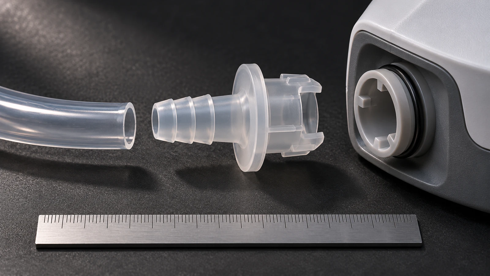
Use a controlled assembly drawing or model to show how the connector is installed and which parts are customer-supplied. State the revision for both the connector and mating components. If the design uses a specified tube material or wall thickness, include that information because the connector’s engagement can depend on the mating part’s compliance. The supplier should not select a tube interface from a nominal label alone. Clear ownership of each dimension makes prototype fit checks useful and prevents a sample from being accepted against an assumed rather than approved mating part.
Separate retention from sealing geometry
Retention features such as barbs, ribs, threads, or locking shoulders serve different purposes from the surface that seals or defines the flow path. The design should state which feature provides retention, which provides a seal, and which limits insertion. If a taper is present, provide the angle or profile definition and its relationship to the bore. Avoid relying on a single outside diameter to control all these functions; local geometry may change along the connector’s length.
Where a connection must be leak-tested or subjected to a force check, the device manufacturer should define the method, fixture, fluid or pressure conditions, sample quantity, and acceptance limits. A supplier should not invent these values or imply that dimensional inspection proves leak-tight performance. The part drawing can control dimensions and surface requirements, while an approved assembly-level protocol controls functional evidence. Keeping those responsibilities separate helps the team request the right manufacturing scope.
Specify the polymer and its condition precisely
Medical connectors can be made from different thermoplastics depending on design requirements. The approved specification should identify the exact resin grade, color or additive requirements, conditioning, traceability, and any required material documentation. Naming a broad polymer family is not enough when suppliers could source grades with different processing or mechanical characteristics. Do not treat a material as medically approved solely because it is commonly used in healthcare products.
Material behavior interacts with wall thickness and connector geometry. A thin wall around the bore may fill and cool differently from a thick grip or barb region. Moisture conditioning, temperature, and the mating tube may influence dimensions or assembly behavior, but only the device’s design and validation plan can define what matters. A supplier can report the resin used and process conditions within the agreed scope. Claims about biocompatibility, sterilization, or regulatory status must be tied to documented evidence supplied and approved by the responsible manufacturer.
Select molding or machining for the development question
CNC machining can be appropriate for early design studies, limited quantities, or connectors whose geometry and material allow the specified features to be produced from stock. It can help evaluate bore, shoulder, and assembly interfaces without committing to a production mold. However, a machined sample does not reproduce molding flow, gate vestige, weld lines, shrinkage, or tool-related variation. Record what the prototype is expected to evaluate and what it cannot represent. Medical suction tube connector manufacturing is best selected after the tube fitting interface, resin specification, and development question are clear.
Injection molding may better match the intended production material and geometry when quantities and design maturity justify tooling. For a development program, low-volume tooling can support iteration while maintaining a molded-part route. The decision should account for design revisions, mold investment, feature access, expected release quantities, and inspection needs. Jucheng’s low-volume injection molding et fabrication de prototypes pages provide process context; the customer’s released drawing and validated requirements define acceptance.
Review mold details around the bore and port
For molded connectors, identify the parting line, gate location, ejector marks, draft, and any cores that form internal passages. These features may influence sealing or mating zones, so the drawing or appearance specification should define where marks or flash are acceptable. Internal cores also need a practical method for release and inspection. A nominally simple bore can become difficult to measure if a core leaves a tapered or stepped interior that the drawing does not describe.
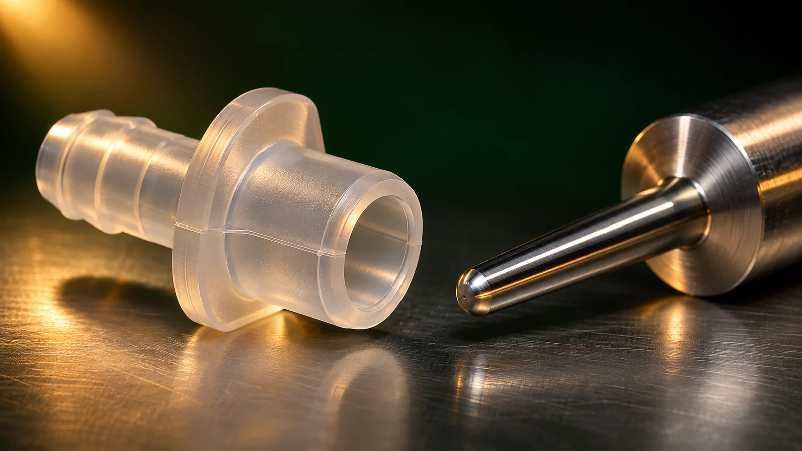
Wall transitions around barbs, flanges, and grip features should be reviewed for fill and cooling behavior. Large thickness changes can produce sink or dimensional variation, while a very thin section may challenge mold filling. These observations are manufacturability prompts, not a substitute for simulation or approved design changes. If the supplier proposes moving the gate, adding draft, or adjusting a wall, record the proposal and obtain customer approval before tooling. The tool should preserve the defined interface rather than silently changing the design to suit convenience.
Make fit and inspection criteria repeatable
Dimensional inspection can include the bore, taper, barb profile, insertion stop, overall length, and any thread or locking feature. Select gauges or measurement methods that contact the intended surfaces without deforming a flexible connector. If a go/no-go gauge represents a mating tube, define the gauge dimensions and what acceptance means. A gauge result is only useful when the reference is controlled and traceable to the design requirement.
For first articles, identify material lot or grade information when required, drawing revision, measurement method, and each reportable feature. If the product design calls for assembly testing, link the test record to the exact component and mating part used. Do not merge dimensional results with an unapproved flow or leak claim. When a connector is flexible, the inspection plan should clarify whether it is measured in free state or under a specified condition. Such details make results comparable across tooling revisions and suppliers.
What information belongs in the supplier package?
Send the connector and assembly drawings, 3D model, mating tube specifications, material grade and condition, required color or finish, quantity by release, development stage, and inspection documents. Identify sealing, retention, and stop features separately. Include any customer-defined test method with its fixture and acceptance criteria, or clearly state that testing is outside the supplier’s scope. A medical suction tube connector manufacturing RFQ should separately identify the sealing surface, retention feature, tube specification, and any customer-defined test.
Ask for feedback on core access, parting-line location, draft, wall transitions, flash zones, and the measurement of the internal bore. State whether the quote should include mold design, tooling, sample runs, secondary machining, or assembly. If a material or interface is not yet released, flag it so the supplier’s assumptions are visible. A precise package lets the team compare proposals and plan the next engineering decision without turning a manufacturing quotation into a claim of finished-device validation.
For the wider process context, see medical device manufacturing processes; the device manufacturer remains responsible for product validation and acceptance requirements.
Frequently asked questions
Can a dimensional report prove that a suction connection will not leak?
No. Dimensional results and leak testing answer different questions. The device manufacturer must define any functional test and its acceptance criteria.
Is a machined polymer prototype equivalent to a molded connector?
It can check selected geometry and fit, but it does not reproduce molding effects. State the prototype’s purpose and limits in the sample plan.
Can the supplier select a medical-grade resin?
The customer’s approved specification controls the resin. Supplier input can support review, but grade changes and compliance claims require documented approval.

